
This article was contributed to the Roboflow blog by Mason, a high school student interested in the technologies that drive the modern world. He plans to pursue mathematics and computer science.
Image segmentation is not only useful in two dimensions. Segmentation can be used to aid 3D model generation as well. This works by finding edges and converting to computer generated meshes. Tools such as these are beneficial to professionals and hobbyists alike.
Project Overview
In this blog post, we will walk through a project that takes an image of a vase and segment the edges. After calculating the midline segment, it will generate a 3D vase mesh automatically by layering different sized cones.
For this project, I used Node.js with packages such as Three.js and Roboflow’s inference helpers.
In this guide, we will walk through the high level steps that describe the project.
Step #1: Build vase segmentation model
First, sign up for Roboflow and create an account.
Next, go to workspaces and create a new object segmentation project. This will be used to segment vases that the user uploads. Customize the project name and annotation group to your choice.
Next, upload images to use for annotation. Be sure to add a wide range of different styles and environments to ensure model integrity. Now add the images to the dataset for annotation.
You now annotate each image. This can be done using Roboflow’s smart polygon feature or by manually drawing the bounding polygon. It may be easier to share the annotation load with a friend. Roboflow has this feature built in. However, you can also assign all images to yourself for annotation
Once we have our annotations and images, we can generate a dataset version of segmented images. Each version is unique and associated with a trained model so you can test out different augmentation setups.
Step #2: Train vase segmentation model
Now, we can train the dataset. Roboflow provides numerous methods for training. You can train using Roboflow, allowing for special features such as compatibility with Roboflow’s javascript API.
In this case, I used this Colab notebook which uses YOLOv8. Although YOLOv11 is newer, I opted to use v8 due to past success with this format. These notebooks provide great step by step directions and explanations. Once training is completed, it makes it easy to validate and upload the model back to Roboflow.
Step #3: Setting up client segmentation
First, I used Node.js’ express package to generate a static user interface.
Using express-fileupload, the user can send an image back to the Node server. Now, we can use the Axios package to send our image to the Roboflow model we trained.
First, obtain your Roboflow private API key from the settings panel -> API Keys page. Remember to keep this private. The image variable should be the video frame we just saved. You can read it using Node.js’ filesystem API:
import fs from 'fs';

const IMAGE = fs.readFileSync('/path/to/fieldframe.jpg', {
        encoding: 'base64'
    });
Next, we can call the Roboflow API to segment objects.
In the code snippet below, change the URL variable to the URL of the segmentation model you trained. For example, I used https://detect.roboflow.com/bottles-4qqsl/1 as my model.
axios({
    method: 'POST',
    url: URL,
    params: {
        api_key: API_KEY
    },
    data: IMAGE,
    headers: {
        'Content-Type': 'application/x-www-form-urlencoded'
    }
}).then(function (response) {
// Segmentation points are received here
    console.log(response.data);
}).catch(function (error) {
    // In the case of an error:
    console.log(error.message);
});
Now, we receive an array with points along the edge of the vase. To start, I merged the points by distance in order to decrease the polygon size:
// Merge by distance
    let mergeDistance = 10;
    for (let i = 0; i < points.length; i++) {
        for (let p = i + 1; p < points.length; p++) {
            if (getDistance(points[i], points[p]) < mergeDistance) {
                points[i].x = getMiddleValue(points[p].x, points[i].x);
                points[i].y = getMiddleValue(points[p].y, points[i].y);
                points.splice(p, 1);
                p--;
            }
        }
    }
Keep in mind that because the vase should be perfectly uniform, we only need one half to generate the model. The drawing below illustrates this:
To take only the left side of points, I sorted the array of points by their x positions, found the distance between the largest x and the smallest x values, took the midpoint, then created a new array only containing points with x values less than the midpoint x value. Sorting them by y value reorders them into the proper vase position:
let sortedArray = [...points].sort((a, b) => a.x - b.x);

    let maxWidth = sortedArray[sortedArray.length - 1].x - sortedArray[0].x;
    let midpoint = maxWidth / 2 + sortedArray[0].x;

    let leftSidePoints = [];
    for (let i = 0; i < points.length; i++) {
        if (points[i].x < midpoint) {
            leftSidePoints.push(points[i]);
        }
    }
    leftSidePoints.sort((a, b) => b.y - a.y);
Now, we have enough information to generate the vase mesh. For this process I opted to use Three.js, a popular 3D framework for the web and beyond. After installing using npm, I set up the initial scene:
import * as THREE from 'three';
import { GLTFExporter } from 'three/addons/exporters/GLTFExporter.js';
import { Blob, FileReader } from 'vblob';

// Three js part
let scene = new THREE.Scene();
scene.name = 'Vase';
let material = new THREE.MeshBasicMaterial({ color: 0xffff00 });
Now we create an algorithm to generate the mesh. Although not efficient, I decided to approach the problem by iterating through each point sorted by height, starting at the bottom and climbing up the vase. For each point besides the top, I generated a cone mesh with radii from the current point and next point’s x values relative to the midpoint x value. Then I positioned the cone in the scene to properly layer each section.
The first part of the plan was finding each cone’s height. The following code does this:
let heights = [];
for (let i = 0; i < leftSidePoints.length - 1; i++) {
    heights.push(Math.abs(leftSidePoints[i + 1].y - leftSidePoints[i + 0].y));
}
Now we iterate through each height value and create a cone using Three.js:
let onPosition = 0;
    let lastPosition = 0;
    for (let i = 0; i < heights.length; i++) {
        let tempHeight = heights[i];

        let geometry = new THREE.CylinderGeometry(midpoint - leftSidePoints[i + 1].x, midpoint - leftSidePoints[i].x, tempHeight, 32, 1, false);
        let cylinder = new THREE.Mesh(geometry, material);

        let nextPosition = onPosition + (lastPosition / 2) + (tempHeight/2);
        cylinder.position.set(0, nextPosition, 0);
        lastPosition = tempHeight;
        onPosition = nextPosition;

        scene.add(cylinder);
    }
The positioning algorithm is tricky to understand. In summary, this method ensures that each section is flush above and below.
Now that we have all cones in the scene, all that’s left to do is export the scene as a gltf file. Gltf is a popular file format for 3D models and scenes, known for being efficient and universally used.
For this, I used the previously installed GLTFExporter. However, this comes with a catch: the GLTFExporter was designed to run on the web, not a Node server. A workaround I found goes as follows:
// Patch global scope to imitate browser environment.
global.window = global;
global.Blob = Blob;
global.FileReader = FileReader;
global.THREE = THREE;
global.document = {
    createElement: (nodeName) => {
        if (nodeName !== 'canvas') throw new Error(`Cannot create node ${nodeName}`);
        const canvas = new Canvas(256, 256);
        return canvas;
    }
};
In essence, this overwrites Three.js methods to use a different FileReader than the FileReader that only works on the web. After this workaround we can export the scene using the following code:
const params = {
      trs: false,
      onlyVisible: true,
      binary: false,
      maxTextureSize: 4096
  };
  const options = {
      trs: params.trs,
      onlyVisible: params.onlyVisible,
      binary: params.binary,
      maxTextureSize: params.maxTextureSize
  };
  let exporter = new GLTFExporter();
  // Parse the input and generate the glTF output
  exporter.parse(
      scene,
      // called when the gltf has been generated
      function (gltf) {
          if (gltf instanceof ArrayBuffer) {
              console.error('Array error');
          } else {
              const output = JSON.stringify(gltf, null, 2);
              saveString(output, 'scene.gltf');
          }
      },
      // called when there is an error in the generation
      function (error) {
          console.log(error);
      },
      options
  );
Although the parameters look complicated, some are optional and mostly the default values anyway. Now we just have to add the saveString method we reference in the code above:
function saveString(text, filename) {
    fs.writeFile(__dirname + '/temp/' + filename, text, function (err) {
        if (err) {
            return console.log(err);
        }
        console.log('File saved.');
    });
}
We now save the gltf file using Node’s built in filesystem package (fs). At this point the project is complete and the model has been successfully exported to 3D. These meshes can be used in many popular modeling applications such as Blender.
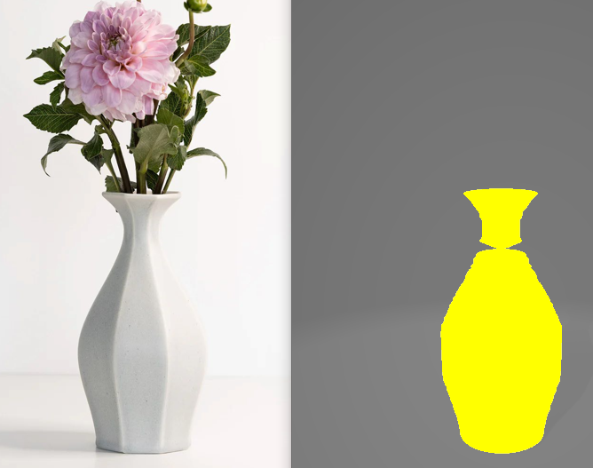
The image on the left below shows an input image. The image on the right shows the segmentation of the vase, calculated using Roboflow.
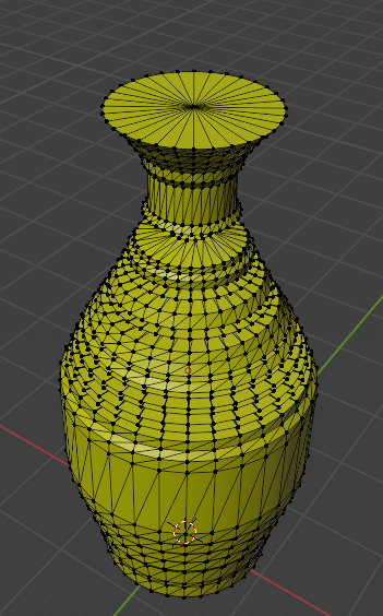
Our application then generates a 3D mask for the object:
There are many ways this project could be improved, such as reducing the amount of vertices, merging the cones into one mesh, or allowing the user to reorient the model. The project assumes the vase photograph is taken at a side view and it is perfectly round. While the project is not perfect, it is a great example of how computer vision can help in unique and generative ways.
Cite this Post
Use the following entry to cite this post in your research:
Contributing Writer. (Oct 8, 2024). Generating 3D Meshes with 2D Image Segmentations. Roboflow Blog: https://blog.roboflow.com/3d-meshes-with-2d-image-segmentations/