
Measuring distance in images with computer vision works by using bounding box or instance segmentation coordinates, applying the Pythagorean theorem to find pixel distances between detected objects, then converting pixels to real-world units via a known reference object. This post walks through detecting cars and soda cans with the Roboflow API, extracting JSON bounding box data, and building a pixel-to-inches ratio calibrated from a reference measurement at a fixed distance. Camera position, image resolution, and bounding box tightness all affect accuracy, so the approach works most reliably when the camera is stationary and boxes are tightly annotated.
Learning Outcomes 💫
By the end of this blog post, you will be able to…
- Know what features make a rectangle or polygon for computer vision applications
- Understand how to calculate distance between two points / objects in an image or video
- Convert pixel distance to real world measurements
- Conceptualize how estimating distance can be applied to other use cases
Components of Computer Vision for Measuring Distance
When a machine learning model detects an object, there is a lot of math that occurs in the background to make it happen. Concepts like gradient descent, backpropagation, activation functions, summing junctions, and more all compound into the ability to detect an object in an image.
While we don’t need to dive into the math of how we detect the object, we will briefly explore what types of inferences there are and how we can use that information to find distance.
Bounding Boxes for Distance Coordinates in Images
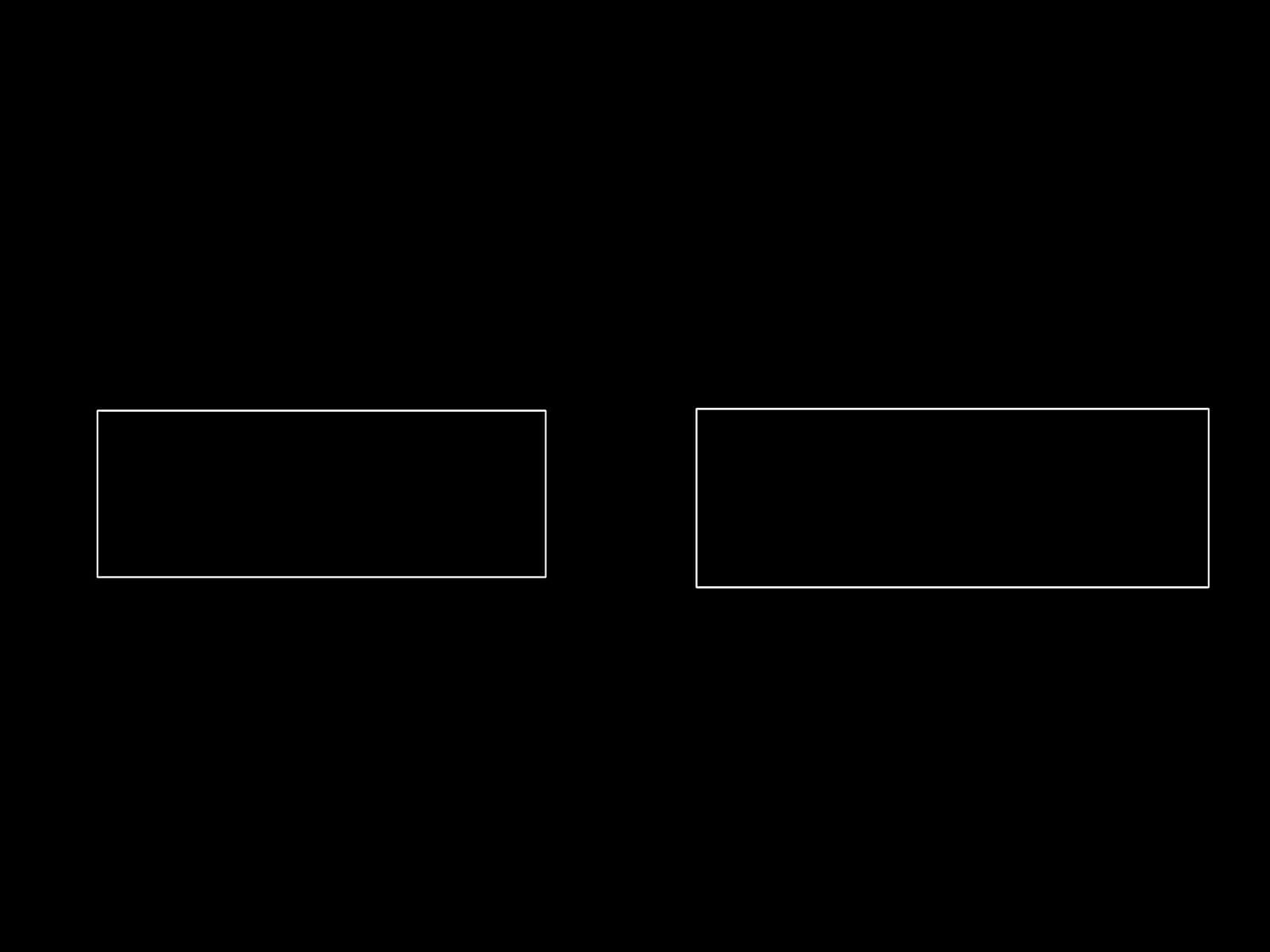
Probably the most prolific and known type of inference is object detection. Object detection uses bounding boxes which consist of information to draw a rectangle around the object of interest.
Some of this information includes the pixel width and height, class name as well as x and y coordinates. We can then use the size information along with the coordinates to determine where all four sides of the rectangle should be drawn.
Using JSON Outputs to Draw Bounding Boxes
To draw a rectangle using cv2.rectange(), you need the top-left corner and bottom-right corner of the rectangle.
This is a JSON example of an object detection response using Roboflow API:
{'predictions': [{'x': 1020.5, 'y': 1568.5, 'width': 1423, 'height': 529, 'class': 'Kia Rio', 'confidence': 0.946, 'image_path': 'test_images\estimate_5_feet.jpg',
'prediction_type': 'ObjectDetectionModel'}, {'x': 3024.0, 'y': 1581.5, 'width': 1626, 'height': 567, 'class': 'Hyundai Elantra', 'confidence': 0.937,
'image_path': 'test_images\estimate_5_feet.jpg', 'prediction_type': 'ObjectDetectionModel'}], 'image': {'width': 4032, 'height': 3024}}
JSON object detection response
We can then take this JSON information and convert it using Python into bounding box coordinates. With these coordinates, we can use OpenCV to draw a rectangle where an object is on the image, like so.
Instance Segmentation for More Precise Object Measurements
Instance segmentation, an advanced method of segmentation, deals with locating instances of objects, defining their bounds, and assigning a class name to that object.
Whereas traditional segmentation focused exclusively on regionality of an object, instance segmentation combines features from object detection and classification to supercharge its inference capabilities.
Large-scale applications of these models can be found in self-driving cars, medical imaging, aerial crop monitoring, and many other real-world use cases.
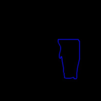
Understanding a Polygon as an Array of X and Y Coordinates
A polygon is a closed, two-dimensional, flat or planar structure that is circumscribed by straight sides. There are no curves on its sides. The edges of a polygon are another name for its sides. A polygon's vertices (or points) are the places where two sides converge.
This is an example of an array of x and y coordinates from inference segmentation that makes up the points of a polygon:
[{'x': 314.0, 'y': 324.1}, {'x': 306.0, 'y': 324.1}, {'x': 302.0, 'y': 318.1}, {'x': 289.0, 'y': 322.1}, {'x': 273.0, 'y': 322.0}, {'x': 265.0, 'y': 320.0},
{'x': 264.7, 'y': 302.0}, {'x': 261.9, 'y': 296.0}, {'x': 261.7, 'y': 279.0}, {'x': 256.0, 'y': 253.0}, {'x': 254.8, 'y': 234.0},
{'x': 253.0, 'y': 232.1}, {'x': 251.1, 'y': 233.0}, {'x': 249.0, 'y': 240.1}, {'x': 245.9, 'y': 239.0},
{'x': 244.0, 'y': 235.0}, {'x': 244.0, 'y': 224.0}, {'x': 249.7, 'y': 204.0}, {'x': 249.7, 'y': 192.0}, {'x': 239.0, 'y': 173.0}, {'x': 239.0, 'y': 162.9},
{'x': 321.0, 'y': 162.7}, {'x': 327.2, 'y': 170.0}, {'x': 327.0, 'y': 243.0}, {'x': 319.3, 'y': 277.0},
{'x': 316.3, 'y': 300.0}, {'x': 316.0, 'y': 320.0}, {'x': 314.0, 'y': 324.1}]
x and y coordinates from inference segmentation
In computer vision, we can use these points to draw the polygon by feeding it to a function like cv2.polylines() in python. This will take the points above and draw lines from each coordinate to the next until a fully closed polygon is built as displayed below.
Calculating Distance Between Points using Pythagoras
To calculate distance between two points we can use the Pythagorean Theorem to solve for any side of the polygon.
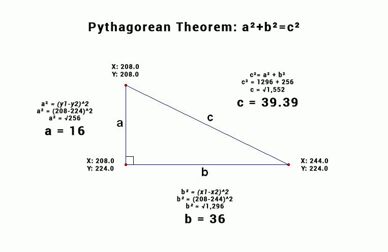
Often in computer vision problems you are solving for side c, because you are trying to calculate the distance between two object points that are on different horizontal and vertical planes.
By using the coordinates (x1, y1) representing the right most point on the triangle and coordinates (x2, y2) representing the top most point.
We can use a^2 + b^2 = c^2 to determine the distance between two points.
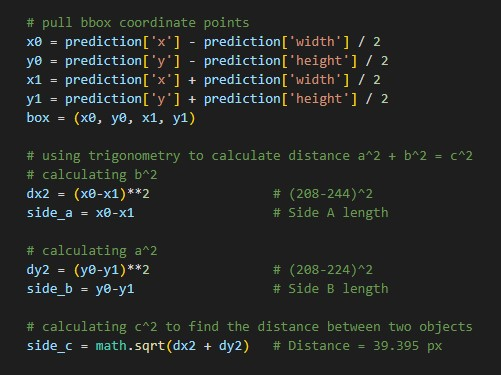
Pixel Distance Coding Example for a Triangle
Using the above triangle, let's see an example:
Using Computer Vision to Measure Distance Between Cars
In the real world, we don’t measure things using pixels so we need to convert this pixel distance into something humans can use.
Since I’m coding out of the USA, we will show the process for converting pixels to inches. You are more than welcome to use centimeters or any other measurement you would like. The only thing you need to know is the real world measurements of one of the objects you are trying to detect. Then you can use that ratio to measure other objects or lines you draw on the screen.
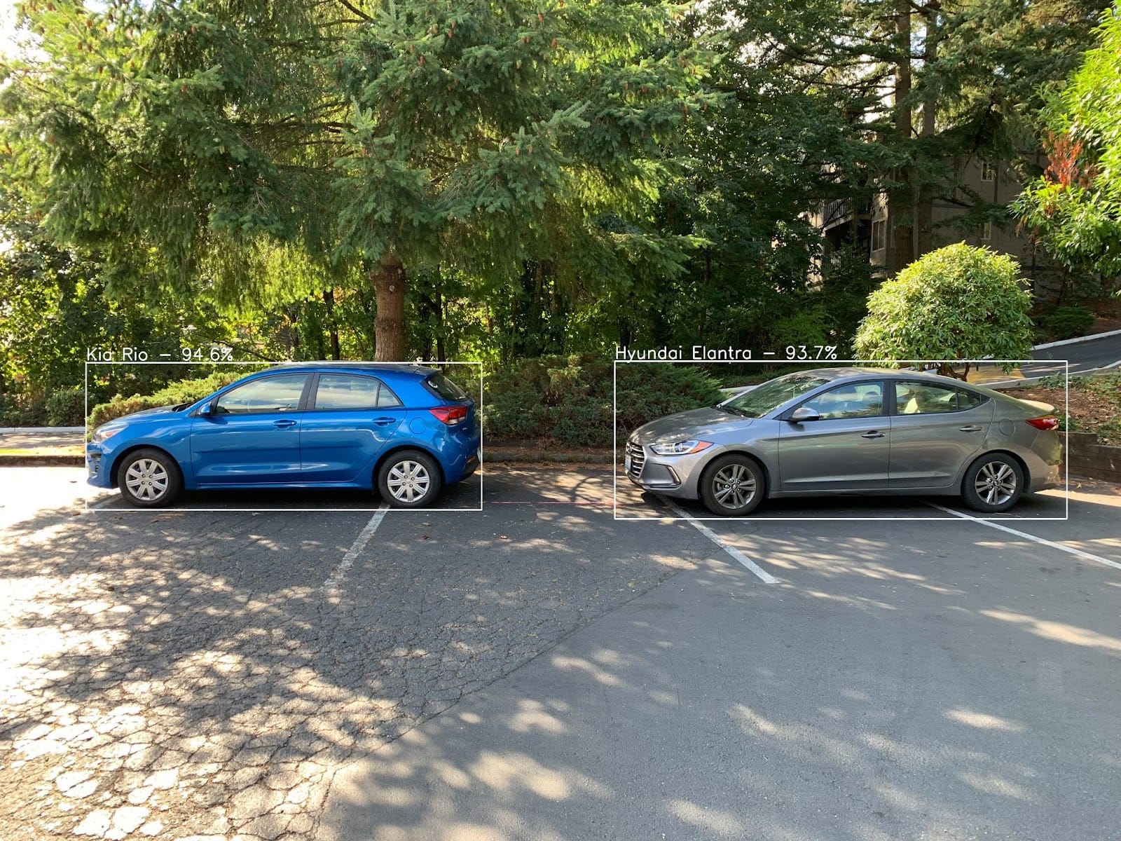
So how would we go about measuring the distance between these two cars? Here’s a link to the GitHub and car detection dataset and model that was used in the following example.
Converting Pixel Distance to Inches
In our demo example using the triangle, the pixel distance was approximately 39px. In our real world case, after running inference and using the Pythagorean Theorem, we can determine that the current pixel distance is 479px from one box of the car to another.
Next we need to know the approximate size of at least one of the objects in the photo. Fortunately, using Roboflow’s inference API, we can determine that the Hyundai Elantra is approximately 1590px wide. We also know that the Kia Rio is approximately 1423px wide.
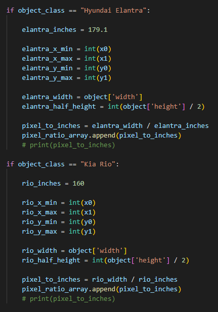
Now that we have the approximate pixel distance between the cars, and all the car’s pixel width, we will use the manufacturing documentation to conclude how wide the Hyundai Elantra and Kia Rio are in inches. The Elantra is about 179.1 inches and the Rio is 160 inches.
We can take the pixel distance of the cars and the inches distance of the same object to create a relatively accurate pixel to inches ratio.
1590px / 179.1 inches = 8.877px/inch
1423px / 160 inches = 8.893px/inch
Average Pixel Ratio = int((8.877+8.893) / 2)
Average Pixel Ratio = 8px/inch
Since we can’t measure or draw in between pixels, we have chosen to round down. Making the pixels_to_inches ratio 8px per inch. For your distance measuring use case, you may choose to round up.
Inference was run on a photo resolution of 4032 x 3024 pixels. The higher the resolution of the photo, the more accurate the distance measurement should be because the more pixels you have to work with.
Converting pixel distance to inches example:
Applying the Pixel Ratio Concept to Measure Between Bounding Boxes
Now that we know every 8px equals an inch, we can start to represent the distance between the cars in inches by using our pixel ratio.
479px / 8px = 59.875 inches
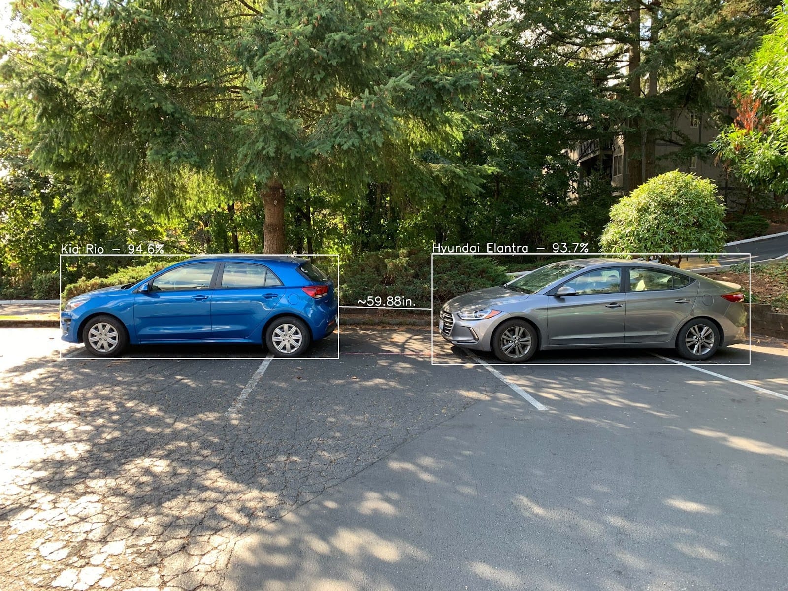
Cars at Approximately 5 Feet Apart
Testing the Pixel Ratio Concept at a New Distance
After successfully calculating the distance between the cars at 5 feet. Let's move the cars to an approximate distance of 10 feet and reapply the calculations.
The inference API tells us that the Elantra is approximately 1462px wide and the Rio is about 1209px wide. By dividing the px width by the known inches width of the cars, we can determine the pixel ratio once more.
1462px / 179.1 inches = 8.16px/inch
1209px / 160 inches = 7.556px/inch
Average Pixel Ratio = int((8.16+7.556) / 2)
Average Pixel Ratio = 7px/inch
Using the trigonometry from before, we can determine the distance between the boxes of the cars is approximately 756px.
756px / 7px = 108 inches
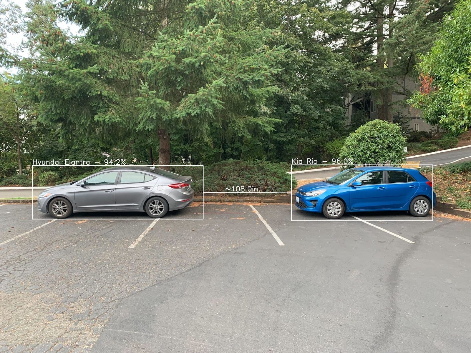
Cars at Approximately 10 Feet Apart
Using Computer Vision to Measure Objects at a Fixed Distance
By using the same pixel ratio theory that was used for measuring cars, it can now be used to measure a water bottle and an action figure of unknown height.
This process will show how to convert pixels to inches, but the concept works with other measurements as well. The only thing you need to know is the real world measurements of one of the objects you are trying to detect. That object is internally referred to as a calibration object. For this example, we will be using a soda can as our calibration object because they are reliably manufactured to be exactly 4.83 inches tall.
By using this known height, the calibration object allows the application can set it's pixel ratio and can adjust the ratio if moved to a new location. After calibration, by placing an another object the same distance away from the camera, it will attempt to measure that object.
Calibrating CV Application with Soda Can to Measure Other Objects
Addressing Nuances of the Soda Can Measurement Application
While this application is awesome, there are some physical limitations to the current code. As the code is written today, the position of the soda can matters. This is because we use the bounding box in real-time to adjust the pixel ratio to the known height of the can. Which is why the inches of the soda can slowly adjusts to 4.83 after a couple seconds. After calibration, we need to place the the object we are measuring the same distance from the camera, in order to maintain proper scale.
If the figure were 2x closer to the camera than the can, then the pixel to inches ratio would not be properly scaled for the figure. Thus, the measurement of the figure would be incorrect. Maintaining similar distance of objects is how we are able to rely on the bounding boxes size to predict the height of the object.
Potential Improvement to this Application and Future Applications
Applying the reference concept works at a fixed distance, but what if we need to measure an object at a different distance. Well one of the solutions would be to get multiple reference objects and then build some logic on when to use each reference. This way you try and solve the distance problem by adjusting to the closest reference object. While this isn't perfect, it will perform much more accurately than just taking reference from one distance.
Another potential solution would be to get another metric to reference off of. For example, we can attach a LiDAR or distance sensor to the front of the camera to get another metric to average off of. So instead of relying solely on the bounding box measurement to determine the pixel ratio, the distance can be added into the equation as a weight. By having a reference object in conjunction with a distance measurement, the application in theory should be able to obtain pretty precise measurements.
The last potential solution would be to use multiple cameras. One for facing vertically to the environment and one facing horizontal to the environment. This way we can use the cameras as a sort of X and Y axis to determine where the object is in the field of view for each camera. By having access to multiple planes of measurement we can start to develop logic for measuring the object potentially without a reference measurement. While I personally haven't tested this multi-camera theory, I have high hopes that someone else already has or will.
Measure Objects at a Fixed Distance - Code
Requires: OAK Camera and Trained Roboflow Model + API Key
from roboflowoak import RoboflowOak
from numpy import mean
import cv2
import time
import numpy as np

width = 640
height = 640
dim = (width, height)
size = (width, height)

# font
font = cv2.FONT_HERSHEY_COMPLEX_SMALL
org = (25, 25)
fontScale = 1
color = (255, 0, 0)
thickness = 1

fpsArray = []
averageFPS = 0

pixel_ratio_array = []
averagePR = 0

# Define the codec and create VideoWriter object.The output is stored in 'outpy.avi' file.
out = cv2.VideoWriter('output.avi',cv2.VideoWriter_fourcc('M','J','P','G'), 30, (640, 640))

if __name__ == '__main__':
    # instantiating an object (rf) with the RoboflowOak module
    # API Key: https://docs.roboflow.com/rest-api#obtaining-your-api-key
    rf = RoboflowOak(model="MODEL-AI", confidence=0.4, overlap=0.3,
    version="1", api_key="API-KEY", rgb=True,
    depth=False, device=None, blocking=True)
    # Running our model and displaying the video output with detections
    while True:
        t0 = time.time()
        # The rf.detect() function runs the model inference
        result, frame, raw_frame, depth = rf.detect()

        # print(result)

        predictions = result["predictions"]

        # print(predictions)

        for object in predictions:

            # print(object.json())
            object_JSON = object.json()

            object_class = str(object_JSON['class'])
            object_class_text_size = cv2.getTextSize(object_class, font, fontScale, thickness)
            print("CLASS: " + object_class)
            object_confidence = str(round(object_JSON['confidence']*100 , 2)) + "%"
            print("CONFIDENCE: " + object_confidence)

            # pull bbox coordinate points
            x0 = object_JSON['x'] - object_JSON['width'] / 2
            y0 = object_JSON['y'] - object_JSON['height'] / 2
            x1 = object_JSON['x'] + object_JSON['width'] / 2
            y1 = object_JSON['y'] + object_JSON['height'] / 2
            box = (x0, y0, x1, y1)
            # print("Bounding Box Cordinates:" + str(box))

            ## THIS IS WHERE THE PIXEL RATIO IS CREATED ##
            if object_class == "Soda":

                soda_inches = 4.83

                soda_height = object_JSON['height']

                pixel_to_inches = soda_height / soda_inches
                pixel_ratio_array.append(pixel_to_inches)
                # print(pixel_to_inches)

                object_Inches = soda_height / averagePR

                print("SODA INCHES: " + str(object_Inches))

                inches_ORG = (int(x0), int(y0-10))

                frame = cv2.putText(frame, 'Inches: ' + str(object_Inches)[:4], inches_ORG, font, fontScale, (255,255,255), thickness, cv2.LINE_AA)

            if object_class == "Figure":

                figure_height = object_JSON['height']

                object_Inches = figure_height / averagePR

                print("FIGURE INCHES: " + str(object_Inches))

                inches_ORG = (int(x0), int(y0-10))

                frame = cv2.putText(frame, 'Inches: ' + str(object_Inches)[:4], inches_ORG, font, fontScale, (255,255,255), thickness, cv2.LINE_AA)

            if object_class == "Water":

                water_height = object_JSON['height']

                object_Inches = water_height / averagePR

                print("WATER INCHES: " + str(object_Inches))

                inches_ORG = (int(x0), int(y0-10))

                frame = cv2.putText(frame, 'Inches: ' + str(object_Inches)[:4], inches_ORG, font, fontScale, (255,255,255), thickness, cv2.LINE_AA)

        # timing: for benchmarking purposes
        t = time.time()-t0


        # setting parameters for depth calculation
        # max_depth = np.amax(depth)
        # print("DEPTH: " + str(max_depth))

        # resize image
        resized = cv2.resize(frame, dim, interpolation = cv2.INTER_AREA)

        fpsArray.append(1/t)
        averageFPS = mean(fpsArray)
        averagePR = mean(pixel_ratio_array)

        print("FPS: ", 1/t)
        print("PREDICTIONS: ", [p.json() for p in predictions])
        print("PIXEL RATIO: " + str(averagePR) + "\n")

        resized = cv2.putText(resized, 'FPS: ' + str(averageFPS)[:4], org, font, fontScale, color, thickness, cv2.LINE_AA)

        del fpsArray[:-180]
        del pixel_ratio_array[:-180]

        cv2.imshow("frame", resized)

        out.write(resized)

        # how to close the OAK inference window / stop inference: CTRL+q or CTRL+c
        if cv2.waitKey(1) == ord('q'):
            break
Code for Running OAK-D camera using Roboflow Model
Measuring Distance with Computer Vision Summary
This solution showed that it is technically possible to use pixels to measure the distance between objects in a photo.
There are some nuances, like image resolution, to be aware of when using this in practice. You can think of pixels as lines on a ruler. The more pixels you have, the more lines you will be able to see on the ruler. Thus, the more pixels you have, the more likely the measurement will be accurate.
Another learning takeaway is bounding box tightness. Since our use case relies on using the current pixel width to calculate the pixel to inches ratio, we need the boxes to be tightly bound. Having loose bounding boxes can lead to the pixel ratio being over or underestimated, which will skew the results away from an accurate measurement. We recommend using labeling best practices to maintain high quality bounding boxes.
Lastly, for projects where the camera is stationary, you can be more confident that this would work as a solution for measuring distance. Not having to account for the z axis (camera position) means that it is more likely the pixel ratio will hold across measurements. The problem becomes more difficult if you try to measure objects at different camera positions or angles.
Thank you for reading and best of luck for those of you interested in applying this concept on your own projects. Drop any questions (or examples!) in the forum.
Cite this Post
Use the following entry to cite this post in your research:
Tyler Odenthal. (Sep 21, 2022). How to Measure Distance in Photos and Videos Using Computer Vision. Roboflow Blog: https://blog.roboflow.com/computer-vision-measure-distance/