
This article was contributed to the Roboflow blog by Mason.
Object trackers can play an important role in sports game analysis, replay, and live breakdowns. However, these trackers aren’t just limited to traditional sports. They can also be useful for numerous other activities or games.
One niche activity that benefits from this technology are robotics competitions. These systems can greatly improve strategy and analysis of opponents, giving teams an edge over the others. In this article, we cover how object detection models, object segmentation, and object tracking can be applied to map out robot paths in the First Robotics Competition (FRC).
Project Overview
Specifically, this project will run robot object detection on a video the user uploads. Once detections are done running on the frames, each robot will be mapped from the 3d field to a 2d top down diagram of the field.
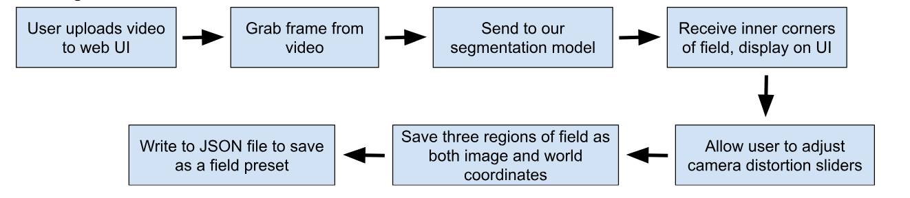
To calculate this, we will make use of field segmentation and simple mathematics. Once finished, the positions will be saved to a JSON file in order to be stored for analysis later on.
For this project, I used Node.js with packages as well as a bit of Python to connect with my Roboflow project.
In this guide, we will walk through the high level steps that describe the project. Full code for the project is available on GitHub.
Step #1: Build robot detection model
First, sign up for Roboflow and create an account.
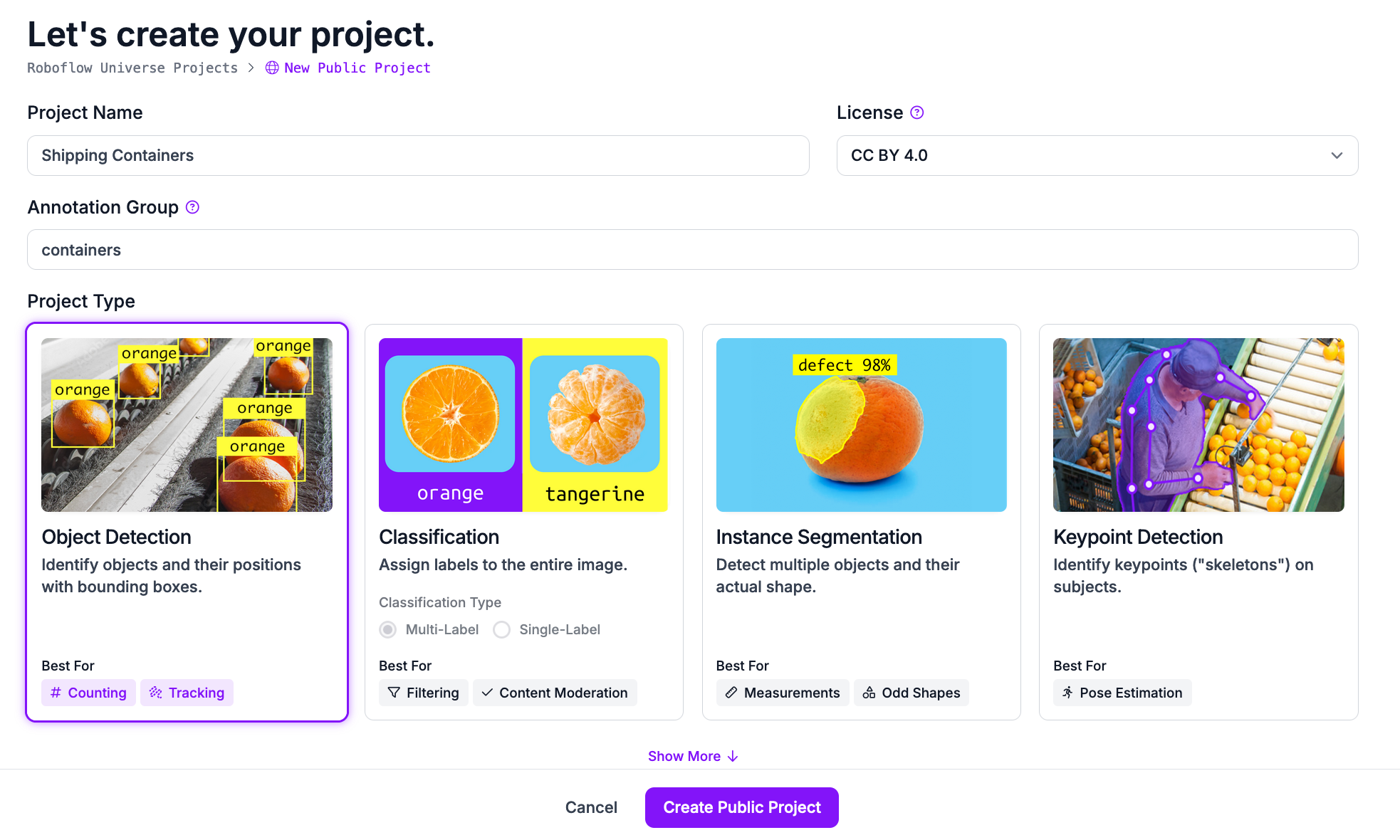
Next, go to workspaces and create a new object detection project. This will be used to detect robots in the video frames Customize the project name and annotation group to your choice.
Next, upload images to use for annotation. For FRC robotics and many other activities, videos of past competitions can be found on YouTube. Roboflow provides a YouTube video downloader, greatly reducing time spent finding images. Make sure to upload multiple different events/competitions to make the model more accurate in different environments. Now add the images to the dataset for annotation.
Next, add the classes for the different types of objects you need the model to detect. In the case of FRC robotics, the class names “Red” and “Blue” work well for differentiating robots on the red team and blue team.
Now annotation can begin. With large datasets, it may be useful to assign annotations to team members. Roboflow has this feature built in. However, you can also assign all images to yourself for annotation.
Using Roboflow’s annotation tools, carefully label the objects and assign the appropriate class. In the case of FRC robotics, I found it easiest to target the robot bumpers instead of the entire robot. This should prevent overfitting, as general robot shapes change each year. Additionally, this allows the model to be reused for other projects such as automated robot avoidance or autonomous defense.
Once we have our annotations and images, we can generate a dataset version of labeled images. Each version is unique and associated with a trained model so you can test out different augmentation setups.
Step #2: Train robot detection model
Now, we can train the dataset. Roboflow provides numerous methods for training. You can train using Roboflow, allowing for special features such as compatibility with Roboflow’s javascript API. However, this method requires training credits.
Alternatively, Roboflow provides Google Colab notebooks to train all sorts of models. In this case, I used this Colab notebook. These notebooks provide great step by step directions and explanations. Once training is completed, it makes it easy to validate and upload the model back to Roboflow.
Step #3: Build field segmentation model
After the robot object detection model is accurately trained, we can move on to training the field segmentation model. This step will allow us to quickly convert 3D world dimensions to 2D image dimensions later on.
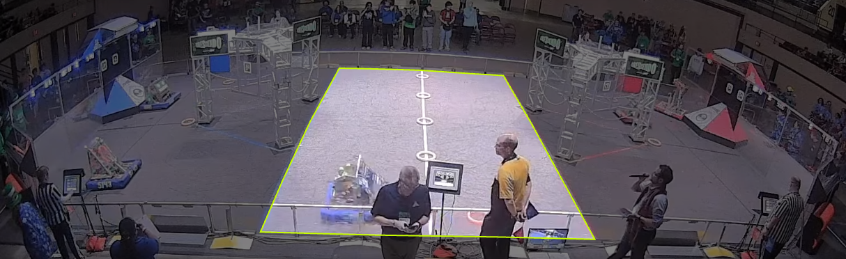
Through testing, I found full field segmentation to be difficult and unreliable. Instead, targeting the central taped region of the field proved to work much more reliably.
For segmentation, I found less images are needed to have it working reliably, as most fields look very similar. However, as the fields for FRC change each year, it is important to use images of current fields, or else the tape lines won’t match up.
Step #4: Build field segmentation model
After using Roboflow’s segmentation annotation tools, we once again train the model. The Google Colab notebook that worked great for me can be found here.


Step #5: Segment fields for coordinate mapping
At this point, we can begin the logic for our project. The first step is to segment the field, as this will allow us to map the robot detection coordinates later on. For segmentation, the process I chose goes as follows:
The web UI aspect adds additional complexity that is not necessary for the project. However, I chose to add it to allow inexperienced users a way to better understand how to use the project. Using Express and Socket.io in my project, I was able to send the user an HTML page and exchange data between the front and back ends of the project.
For this article, we will stick to the bare-bones of how the system works. First, using the Node.js ffmpeg-extract-frames package, we are able to grab one frame from the video:
import extractFrames from 'ffmpeg-extract-frames';

// Millisecond timestamp of frame
var ms = 0

extractFrames({
input: './path/to/video.mp4',
      output: './path/to/destination.jpg',
      offsets: [
      	ms
      ]
 });
This saves the specified frame of the video to your destination. Now, we can use the Axios package to send our image to the Roboflow model we trained. First, obtain your Roboflow private API key from the settings panel -> API Keys page. Remember to keep this private. The image variable should be the video frame we just saved. You can read it using Node.js’ filesystem API:
import fs from 'fs';

const IMAGE = fs.readFileSync('/path/to/fieldframe.jpg', {
        encoding: 'base64'
    });
All that’s left is to change the URL variable to the URL of the segmentation model you trained. For example, I used https://detect.roboflow.com/frc-field/1 as my model.
axios({
    method: 'POST',
    url: URL,
    params: {
        api_key: API_KEY
    },
    data: IMAGE,
    headers: {
        'Content-Type': 'application/x-www-form-urlencoded'
    }
}).then(function (response) {
// Segmentation points are received here
    console.log(response.data);
}).catch(function (error) {
    // In the case of an error:
    console.log(error.message);
});
Now, we receive an array with points along the edge of the field. Finding which of the points are the four corners is as simple as checking the slope to the next point. I started by sorting the points by height and starting at the top point. In the array of points Roboflow returns, the points are sorted along the exterior of the segmented region.
As we move counterclockwise from the top point, the first time the slope from one point to the next is greater than a constant, for example 2, we know that the point is likely a corner point. A similar process can be repeated to find the other corners, going in a circle.
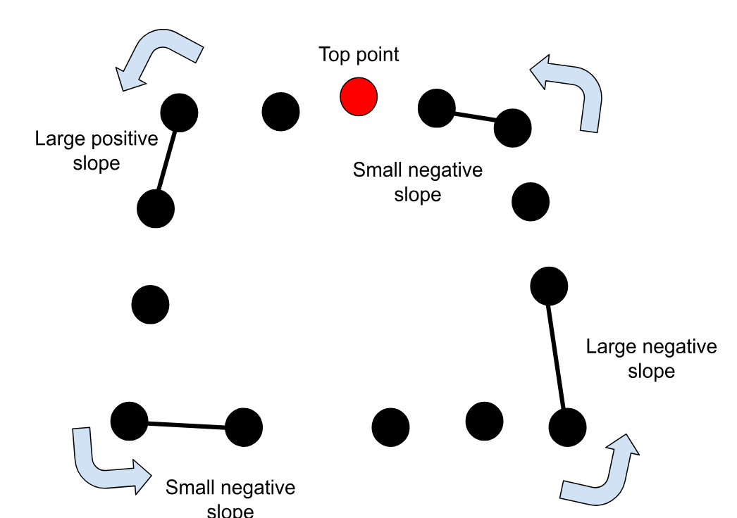
If the top point is not the first element in the array, we will fail to check all points. A quick solution is to create a new array that duplicates the original array three times and finding the second instance of the top point:

Now, we can safely go forwards and backwards in the new large array with the assurance every point will be accounted for.
Once we find the corners of the inner field, we can now predict where the real field corners are. We can go along the horizontal lines formed to find the outer corners on either side. Using multiplication will ensure the perspective remains intact:
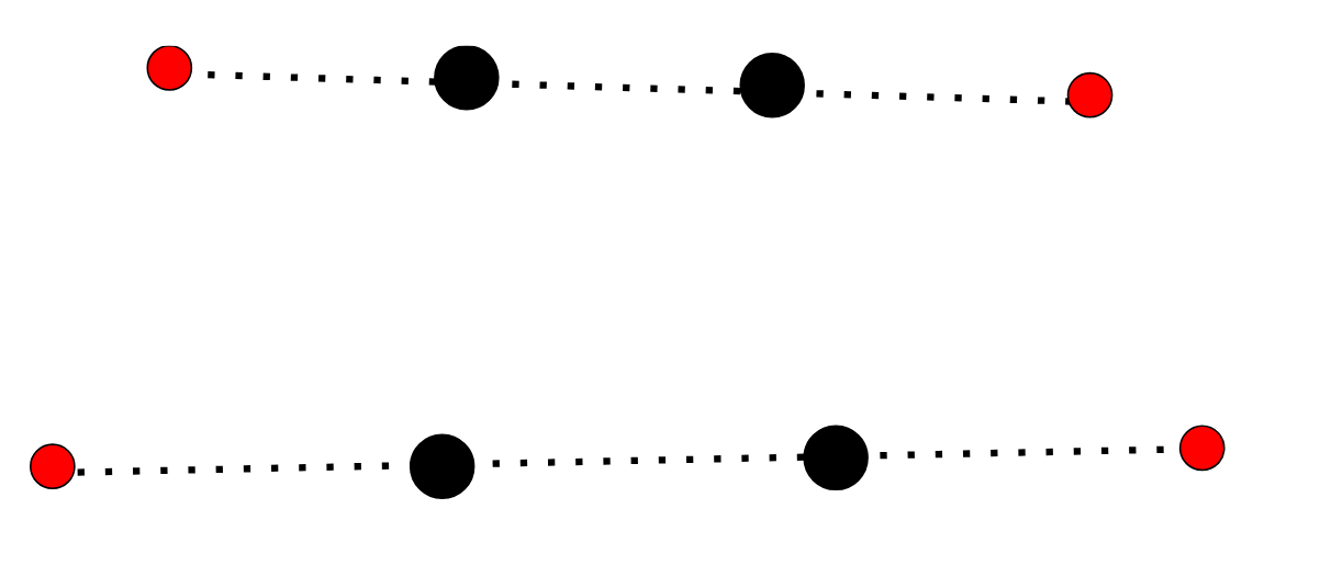
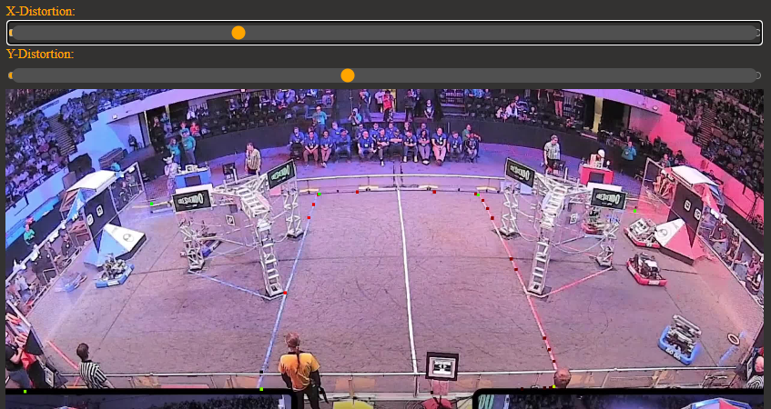
However, because different cameras are used in different competitions, distortion of the field will differ. Fisheye cameras may need to be tuned by sliding the new estimated points (red) up or down depending on the camera used:
After this, the field is roughly divided into three sections: left, center, and middle:
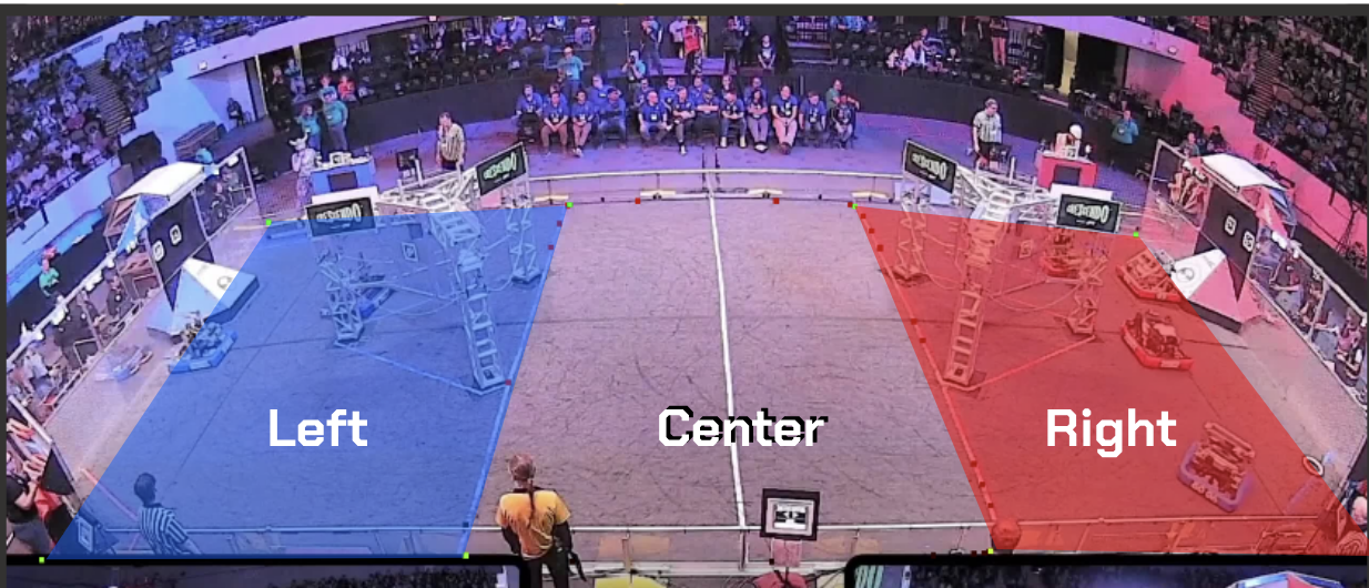
At this point, we know both the screen coordinates as well as the world coordinates, as the tape lines that divide the sections are at known positions, approximately 19 feet from the appropriate edge of the field. So, if we can figure out the robots’ positions on screen, we have enough information to approximate their world positions.
Step #6: Detect robot objects from video
Now we can send the full match videos for detection. In this example, I found it easiest to use Python with Roboflow’s Inference project. The following code will send an entire video for object detection.
Make sure to set the API key to the key obtained earlier, the project name to your object detection project, and the version to the model version you are using (trained iteration).
You can also tune properties such as confidence and overlap thresholds, set below at 50 and 25 respectively. Once the input video path and output json paths are set, you can run this code to get the robot detections saved to a json file.
import os
import sys
import json
from roboflow import Roboflow

rf = Roboflow(api_key="API_KEY")
project = rf.workspace().project("PROJECT_NAME")
model = project.version("PROJECT_VERSION").model

model.confidence = 50
model.iou_threshold = 25

job_id, signed_url, expire_time = model.predict_video(
   "path/to/video.mp4",
    fps=15,
    prediction_type="batch-video",
)

results = model.poll_until_video_results(job_id)

parsed = json.dumps(results, indent=4, sort_keys=True)

# Forgot to add this, add tonight
write_path = “path/to/outputfile.json”

f = open(write_path, "w")
f.write(parsed)
f.close()
Step #7: Estimate detections in world coordinates
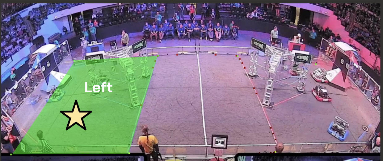
Now that we have the screen coordinates for each detection, we can run an algorithm that uses our three field regions to estimate world positions. While it would be more accurate to use more sections or complex mathematical equations, a simple technique that works very well for this task is finding which region the robot is in and subdividing that region.
After multiple iterations, we have a sound estimate of where the robot is in world dimensions. Take the example below using the star:
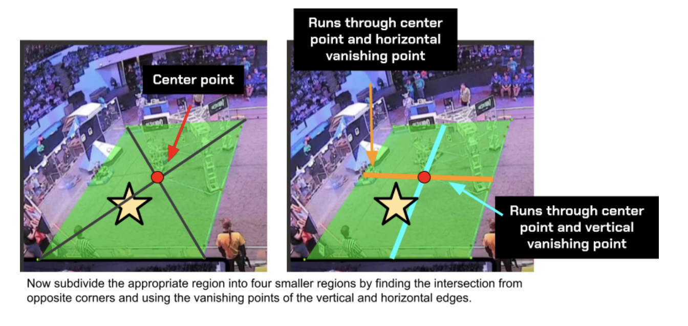
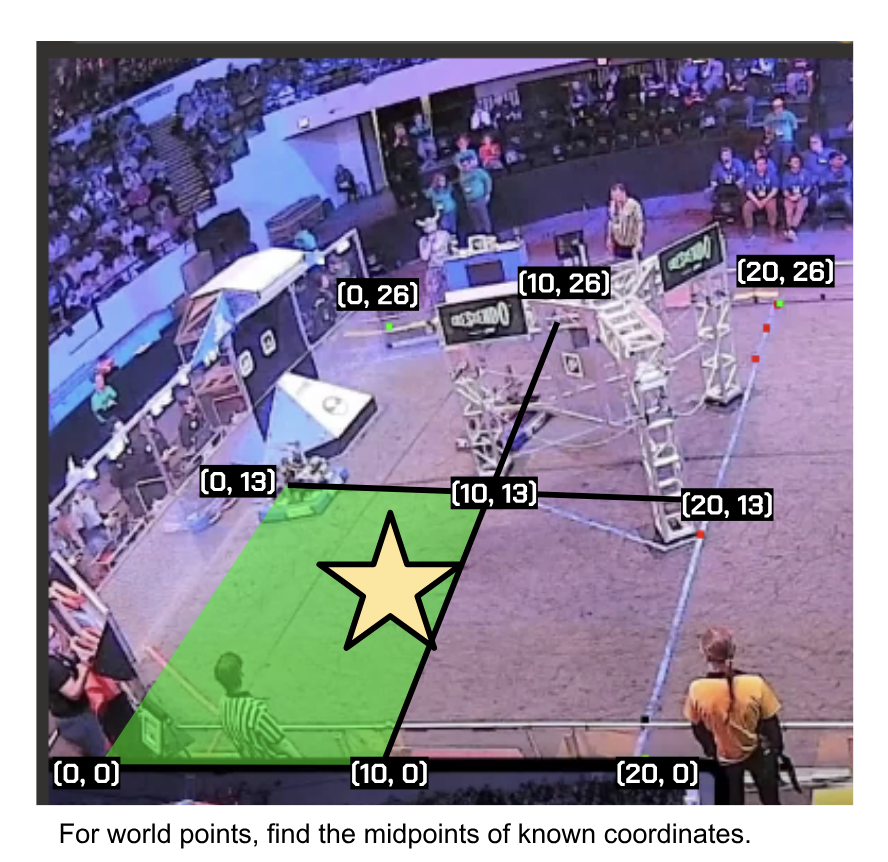
Now find which of the four new quadrants the object is in. Here, the star is in the lower left quadrant. Using this region, repeat the process of subdividing into four regions and finding which the center of the object is in while also finding the midpoints of the world coordinates.
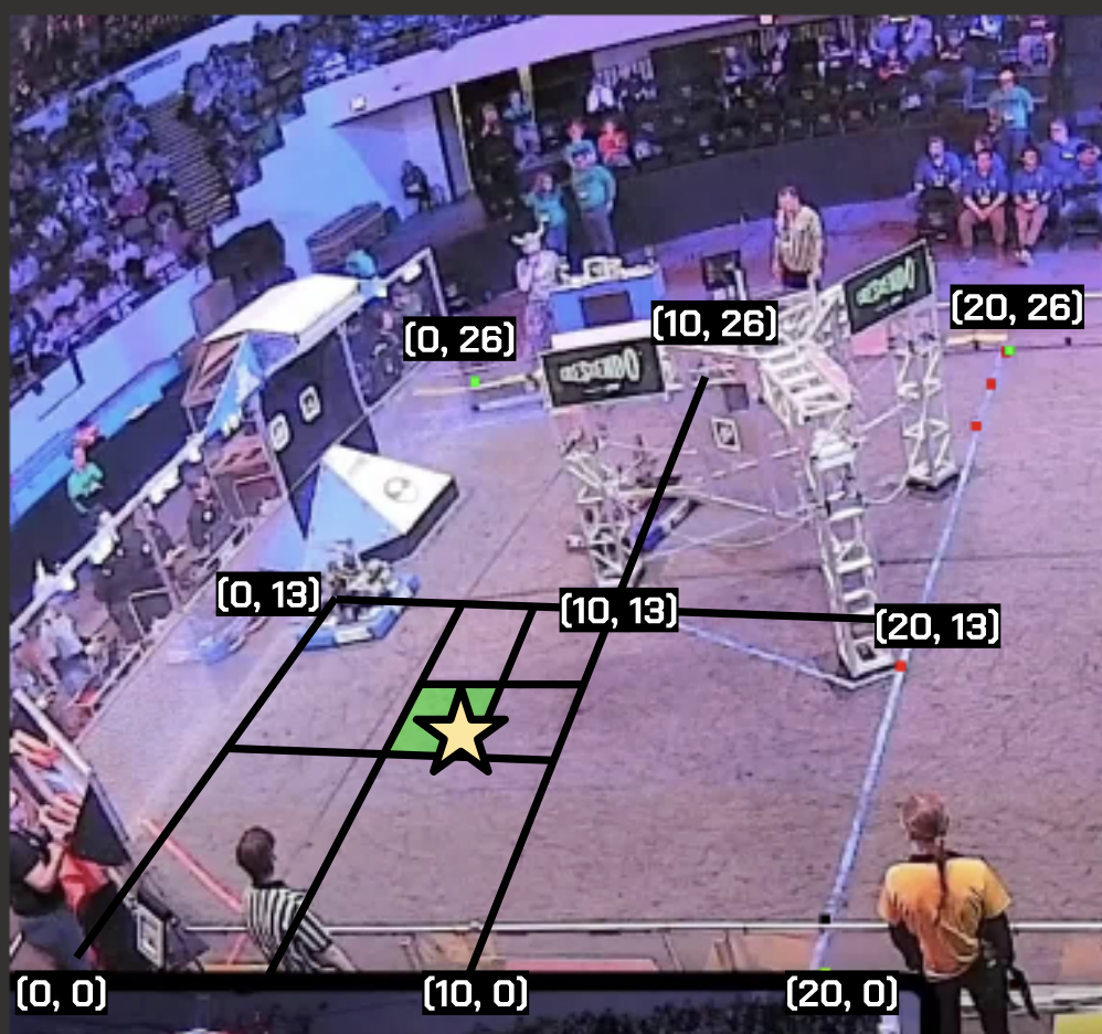
After a few iterations (I used 7), there is little change in accuracy. We can use the bottom point of the last quadrant the object is in, and now we have the object’s world position. All that’s left now is to implement a tracking algorithm.
Step #8: Implement an object tracker
There are many different methods to implement object trackers. They can range from using distances since last detections to accounting for velocities and object size.
For this project, I found that a tracker using only distances worked extremely accurately. For improved accuracy, I tracked each team (red and blue) separately.
iterating through all frames, I found which contained predictions for 3 robots of the desired team. This makes it much easier to handle the tracking, as each prediction should have all three robots for the desired team, eliminating the need for filling in gaps.
I created a new array with three elements for each frame, which will be added to the 2d array of tracked frames. Each robot will get its own index, which will remain consistent for all frames. This means for each frame, the robot in index 1 will be the same. I went ahead and added the first frame of detections to the array.
With the base laid out, for each frame, find the distance from each of the current robots in frame to each of the robots in the previous frame. I added each as a JavaScript object, so I could keep track of the index of both the old and current robot in the detection array. Now, sort the objects based on their distances:
let sortedDistances = [];
for (let current = 0; current < fullAlliancePredictions[i].length; current++) {
        for (let old = 0; old < fullAlliancePredictions[i - 1].length; old++) {
            let currentDistance = (getDistance(fullAlliancePredictions[i][current], sortedAllianceFrames[i - 1][old]));
        sortedDistances.push({
            'current': current,
            'old': old,
            'distance': currentDistance
        });
    }
}

// Sort the array based on object property distance
sortedDistances.sort((a, b) => a.distance - b.distance);
Note the old index and current index of the shortest distance, these are the same robot. So, we can add the current robot object into the old index of the next element in the list of frames. The graphic below explains this process better:
sortedAllianceFrames[i][sortedDistances[0].old] = fullAlliancePredictions[i][sortedDistances[0].current];
Now, we can remove all instances of old index 1 and current index 0, as they are taken:
sortedDistances = sortedDistances.filter(element => element.current !== sortedDistances[0].current && element.old !== sortedDistances[0].old);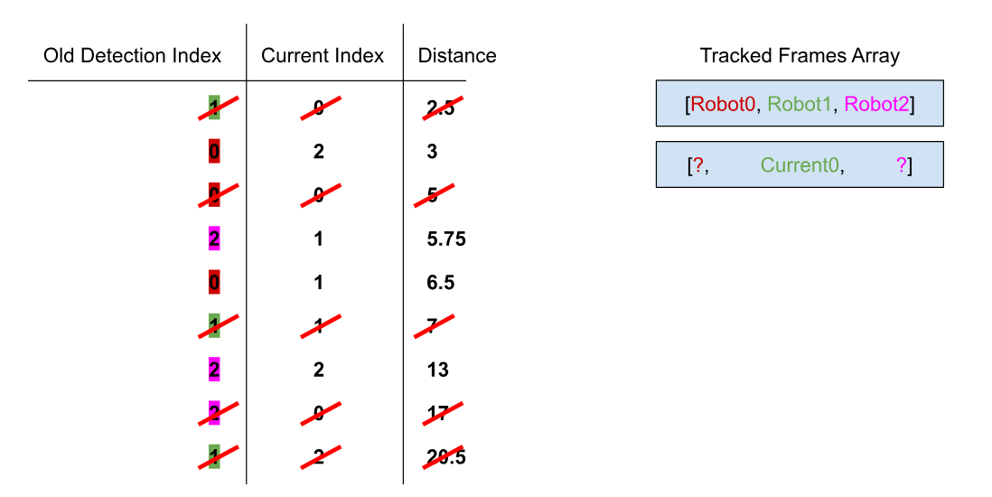
And repeat the process with the next closest distance:
while (sortedDistances.length > 0) {
        sortedAllianceFrames[i][sortedDistances[0].old] = fullAlliancePredictions[i][sortedDistances[0].current];
        sortedDistances = sortedDistances.filter(element => element.current !== sortedDistances[0].current && element.old !== sortedDistances[0].old);
    }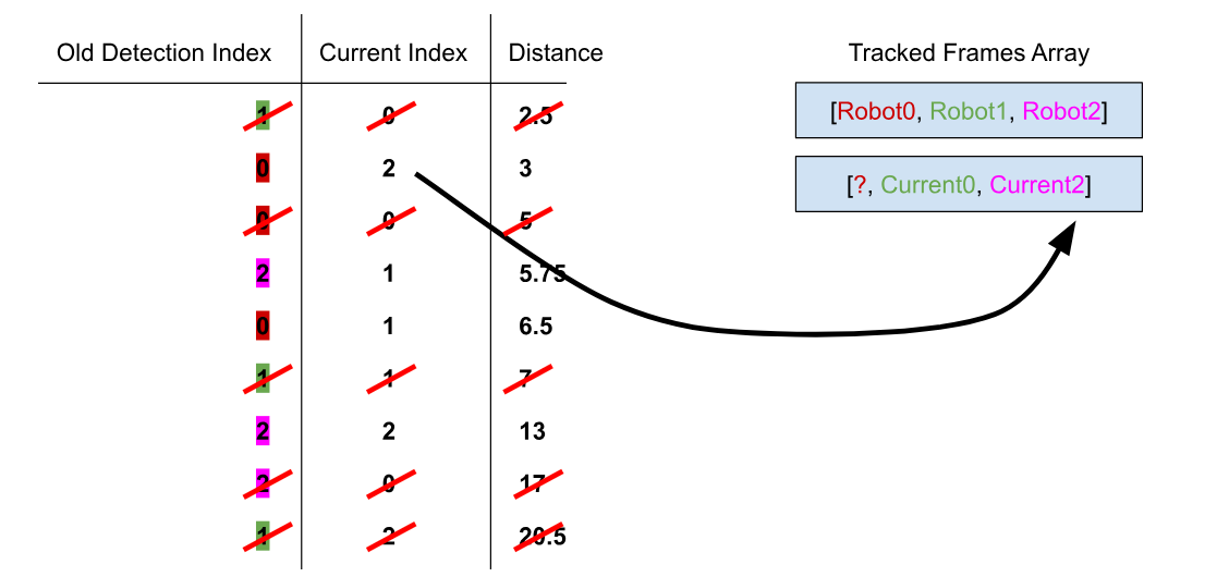
Now, the current 1st element must be the same robot as the previous robot in index position 0. Repeat this process for each frame using the old current as the next old array. This will result in a tracked array of each robot for each frame for the specified team. I repeated this process for both teams, effectively tracking all robots across the frames.
There are some flaws with this system. For example, there are likely frames missing because they only contained 1 or 2 detections. An algorithm could be implemented to smooth this out, as the Roboflow flow detection output contains frame numbers. Additionally, note that the detection itself is metered by Roboflow. You could use your own hardware to perform detections, such as the NVIDIA Jetson or even a device such as an Orange Pi.
Now, we have successfully laid the blueprint for how to track robot positions across a video. This can serve many purposes, such as comparing robot’s autonomous routines or speeds. This can also be applied to numerous other activities and sports using a similar setup.
Cite this Post
Use the following entry to cite this post in your research:
Contributing Writer. (Aug 29, 2024). Mapping Robot Paths in Robotics Competitions with Computer Vision. Roboflow Blog: https://blog.roboflow.com/robot-path-mapping/