
GPS, UWB, BLE, Wi-Fi, and RFID are all radio frequency signals. They are invisible waves bouncing around us constantly. Like the GPS in your phone that knows you're at the coffee shop on 5th Street, any of these signals can be used to pinpoint location.
While the physics of the wave determine range and accuracy, often a trade-off between the two, all signal types can be used to build a GPS-like system. But what happens when you pair that location awareness with the power of sight?
This post walks through how I built a system that combines RF-based tracking, also known as RTLS (Real Time Location Systems), with computer vision to stabilize computer vision tracking and better re-ID objects.
Why Combine RF and Vision?
RF tracking alone can only tell you approximately where an object is and not what is happening to that object. Is a container getting filled with material? Is a worker washing the bus? Is the forklift picking up a pallet?
To add this layer of information, many systems require manual processes completed by workers, such as scanning a pallet. This introduces risk of system degradation due to human error. For instance, someone picks up an item and is supposed to scan it, but they forget, or they're rushed.
RF signals also struggle in certain environments. Metal shelving, dense racking, and stainless steel equipment, often seen in manufacturing, create interference that can throw off location accuracy.
Cameras can offer that extra layer of sight which automates the often manual pieces of RF systems, complimenting existing solutions well.
Cameras are also able to provide the same location tracking technology, immune to the noise caused by metal environments. With the use of projection, the frame coordinates can be converted to a top-down 2D location on a map.
If cameras can also track, why combine the two?
The hybrid approach: RF provides identification, cameras provide precision and visual insight. With solutions where it is critical to log which object is detected, that is where a hybrid solution could be explored.
Although the location from computer vision is precise (<10cm), the object ID retrieved is not always stable. In noisy environments with a lot of metal, camera tracking can offer precise locations. A tag says "I'm object #1 and this is my approximate location." The camera says "There's an object at coordinates (342, 156) on the screen." Together, you know exactly where object #1 is, and what physical actions are occurring.
Note, that in cases where a large visual ID (such as a license plate) could be used in place of an RF identifier, the ideal solution would be to use cameras alone. With visual IDs, the extra stabilization that RF could apply would be negligible and often not worth the extra cost in infrastructure. However, not all environments allow for the use of visual ID. The camera angle, quality, distance, object material, and object orientation could all impact the feasibility of using visual IDs. For example:
- Containers are regularly pressure washed and ID would degrade over time
- Pallets are marked on one side, but are picked up with various orientations
- Clothing that can’t be marked with visual IDs
- A camera oversees an entire bush garage, where the license plate numbers can not be read from the distance
- Dirty environments where the visual ID is frequently covered (think of what your car looks like after driving through a snowy highway)
Building the Proof of Concept
For the proof of concept application, I wanted to establish that I could use RF signals to stabilize the IDs derived from tracking through a camera. I began simple, gathering items I had laying around the house which I could listen to signals from. BLE came first to mind as we are surrounded by countless electronics with BLE (phones, speakers, watches, mouses, keyboards, etc.)
I chose cell phones as my test objects because they're a perfect example of the problem: phones look visually identical. A camera can detect "there's a phone" but can't tell you *whose* phone it is. That's exactly where the beacon signal fills the gap.
The solution I built used a simplified version of standard location systems. Instead of triangulating for a location from three sensors, I only approximated the distance from one sensor only. The app I built listened for BLE IDs and approximated their distance with a linear algorithm based on RSSI. This could help me determine which objects were currently close enough to be seen in the camera frame, and how many objects to ID.
Step 1: BLE Broadcasting
I built an iOS app that broadcasts a custom identifier, mocking my phone as a trackable tag. The app lets me set any ID I want, like "jennifer-iphone" or "test-device-1".
Step 2: BLE Receiving
A Python script running on my laptop listens for these BLE signals. When it detects a beacon, it calculates approximate distance based on signal strength (RSSI). I added Kalman filtering to smooth the readings. As long as I got an approximation of when a device was immediate, near, or far that was enough data to be able to run the POC. Most applications use a log-distance path model:
d = 10 ^ ((TxPower - RSSI) / (10 * n))
BLE code can be tricky and must be written natively on a device. Code from a docker container can not access the device BLE hardware from within the VM. Given this, the easiest solution was to write a native python app on my Mac and publish this data to a MQTT message broker.
Step 3: Object Detection and Tracking
For object detection, I used RF-DETR. This model could identify "cell phone" out of the box, which saved me from having to train a custom model and allowed me to put in more time into the data integration piece.
For tracking, I started with Byte Tracker. Byte Tracker is a workflow block which assigns unique tracker IDs to detections using information such a visual appearance, velocity, and recent frame location to track objects. I made a new version of Byte Tracker labeled v4 which took nearby tag IDs and proximity as input. The key change: the tracker only shows objects when a matching beacon is nearby.
In my version, I maintained a map of tag IDs to corresponding Byte Tracker IDs. If I got a new Object detection I would first check if there were any nearby beacons (phones). If there were no nearby beacons, all object detections would be ignored. Otherwise, I would look up the tag ID in the map. If not present, I would let Byte Tracker generate a new ID and create a new entry in the map. If present, this would override what the Byte Tracker would normally estimate the ID.
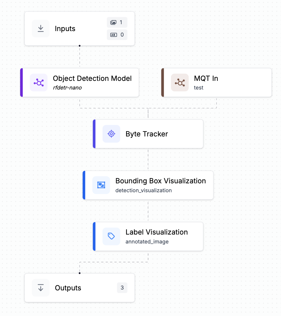
To retrieve the tag ID and distance I wrote a custom python block which subscribed to the MQTT broker and passed the data to Byte Tracker.
Step 4: Comparing Performance
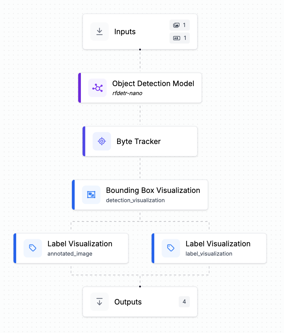
Lastly, I wanted a way to tangibly see the difference my solution made versus the current functionality of Byte Tracker. Therefore, I built two different workflows that were nearly identical. In the first workflow, I used the v3 of Byte Tracker and output the tracker ID’s and bounding boxes.
In the second workflow, I replaced Byte Tracker with my version (v4), and I added a custom block upstream which received the tag ID and distance values from the MQTT server.
To avoid too much noise, I filtered out only the “phone” class for drawing the detection boxes on the front-end. Then, I displayed the output of the two streams side-by-side in a lightweight front-end client.
Findings
Overall, by comparing the two I found that with integrating BLE signals I was better able to:
- Avoid false positives where the model detected and ID-ed phones that did not really exist.
- Stabilize the ID of a single phone as it moves in unusual patterns or high speed.
- Re-ID a phone as it entered and exited the frame.
- Properly distinguish different phones as the entered and exited the frame.
I ran the following tests:
Transmit the ID "jennifer-iphone" and hold the phone in the view of the camera. Both streams identified the phone as one object with an ID. However, the version integrated with the BLE signals proved to be more stable even with little to no motion.
While transmitting a consistent ID, moved the phone within the frame. v3 experienced some flickering while v4 remained a constant ID.
I held the phone in view of the camera, while holding a fake phone in the other hand. This tricked v3 into identifying a second object, while v4 only identified the tagged object.
I held a phone with "jennifer-iphone" ID, then moved the phone to a location where its signal was weaker than the threshold. Then, I picked up a different phone transmitting the ID “sam-iphone”. The v3 Byte Tracker identified it as visually similar and assigned the new ID, while the v4 version correctly identified it as a new object.
Sensor Fusion for Computer Vision Use Cases
When considering integrating with an RF system, keep in mind this approach works particularly well for operations tracking a fixed set of assets over long periods.
- Forklifts that run for years
- Containers that cycle through processes for months
- Tools that live in a facility permanently
- Workers which come in for regular shifts
It's less ideal for high-turnover items that require frequent tagging, since tagging is still a manual process.
Pharmaceutical manufacturing: Metal equipment makes precise RF positioning unreliable, but you don't need precision everywhere, you just need to know when a container enters or exits a room. RF tags detect presence at doorways, then cameras inside track exactly what happens: which container was filled, with what material, at what time. GMP compliance becomes automatic.
Retail: High-value items carry small tags (RFID, BLE, or UWB) while cameras watch the sales floor. Together they answer: Was this item paid for before leaving? Is it displayed in the right location? Where exactly did it go when it disappeared from the shelf? Loss prevention and inventory management in one system.
Maintenance: The combination tracks not just where technicians are, but what they are doing. The tags could contain only information about the technician’s role. For instance, a welder is near car panel X. Then, cameras at workstations recognize tasks (tools being used, panels being attached.) This system could approximate the time it takes to complete maintenance tasks, without asking workers to manually log their time. The system sees the work happening and records it allowing for more optimal planning.
Kitchen Compliance: A BLE app is used to track which chef is currently in the kitchen. The chef could be notified in real-time of their workers' safety violations caught by the camera (not wearing a hair net, no gloves, etc.) making for a proactive solution.
Next Steps
This solution was rather simple and worked well when very few objects were moving in and out of a frame. As the tracking gets more complex, or the tracked space gets larger using proximity alone may not be sufficient.
The BLE proximity was a simple solution and would be sufficient for some use-cases (likely use RFID instead of BLE for price). However, if the use-case requires more advanced tracking, this technology can be extended.
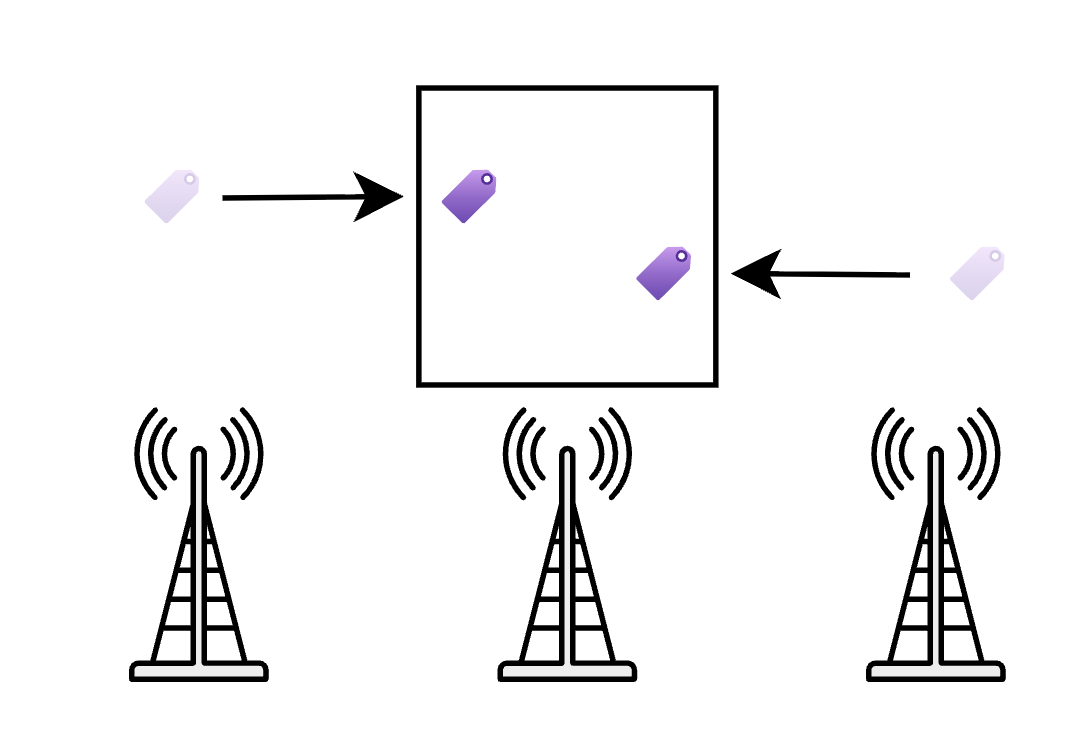
Even by setting up a few extra antennas it is possible to detect the direction where an object entered from. Based on the change of signal strength, we can derive direction. For example, in the diagram below as the tag moved from right to left, the signal received by the far left antenna would increase while decreasing for the far right.
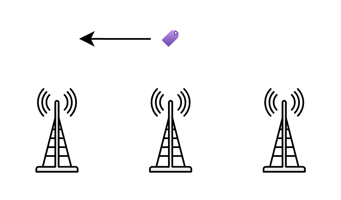
If we have two tags entering the camera’s frame at the same time, due to the direction derived from the changing signal strengths, the system would be able to know which ID belongs to which object. Think of the RF system saying “hi I am tag #1 and I am entering the frame from the left and hi I am tag #2 and I am entering the frame from the right”. Even though they look visually identical, Byte Tracker could use this information to correctly re-ID each object.
This technology can be expanded even further by triangulating signals to give precise X,Y,Z coordinates. With coordinates, the Byte Tracker would be able to properly re-ID several objects entering and exiting a space at the same time.
Different problems demand different levels of precision. In many cases, a simple signal, knowing that an object is nearby, entering, or leaving a space, is enough to unlock meaningful insight when paired with vision. A low cost beacon and a camera can already answer questions that previously required manual scans or human intervention.
For more demanding environments, where multiple identical objects move simultaneously or fine grained spatial awareness matters, higher precision RF systems like UWB or full RTLS become valuable. These systems do not replace vision. They strengthen it by providing stronger identity signals and spatial context when proximity alone is not sufficient.
What makes this approach powerful is its flexibility. You can start simple, using proximity to stabilize identity and reduce errors, and scale up to more sophisticated positioning as the use case demands. By treating RF as a spectrum, from proximity to precise location, and combining it with vision, you can build systems that are both robust and pragmatic, delivering the right level of insight without unnecessary complexity or cost.
Cite this Post
Use the following entry to cite this post in your research:
Jennifer Kuchta. (Jan 27, 2026). Sensor Fusion: Enhancing RTLS with Computer Vision. Roboflow Blog: https://blog.roboflow.com/sensor-fusion/