
Synthetic data can dramatically reduce annotation effort for computer vision projects by generating perfectly labeled images at scale. This tutorial shows how a community contributor used Unity Perception to produce 500 synthetic images of random breadboard circuits (resistors and wires on varied backgrounds) and combined them with 250 manually annotated real images to train a component detection model. The resulting dataset required far less hand-labeling than an all-real approach, and the trained model achieved strong generalization, with Roboflow's Label Assist helping to speed up the remaining manual annotation passes.
This post was contributed to the Roboflow blog by Timothy Evans.
Annotating hundreds or even thousands of images can be time consuming, error prone, and, let’s face it: tedious. A much faster and effective approach might be needed. This is where synthetic data comes in, data that is generated by augmenting and modifying existing data.
Using synthetic data to train computer vision models provides several advantages over manually labeled data, including the ability to almost instantaneously generate large quantities of diverse and cost-effective data while at the same time avoiding potential errors introduced by human annotators. Adding synthetic data to your project can boost your model’s ability to generalize and learn the features you want to identify in an image.
In this post, I’ll show how I made synthetic data involving random circuits to train a computer vision model able to detect resistors and wires on a breadboard.
Step 1: Manual Labeling
The idea was to have an app that allowed you to take a picture of your circuit and have the app see how each component was connected to see if there are any shorts or disconnections.
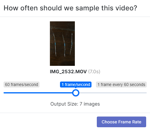
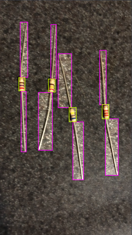
First, I needed to create a computer vision model that can detect circuit components. I started by taking videos of resistors on my iPhone and uploaded them to Roboflow to split up the videos into several images for manual annotation.
After slowly building up my dataset and training several versions I had hundreds of images. Each image had to be manually annotated at first, but then after training my first model I could use Roboflow’s Label Assist to help out. With that said, it can still become tedious to check each image, make small adjustments, and correct errors. This is where synthetic data comes in to save the day.
Step 2: Generating Synthetic Data
Synthetic data can be used together with or in replace of real images. If you have a 3D asset of an object you want your computer vision model to detect, you can easily create synthetic data instead of taking hundreds of pictures.
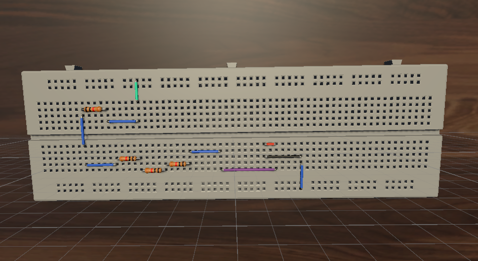
I acquired some cheap 3D models of a breadboard, a resistor, and some wires. Then, I followed the synthetic data with Unity Perception tutorial to generate synthetic data. I used the built-in TextureRandomizer and the RotationRandomizer, along with some custom randomizers for generating random circuits on random table backgrounds.
Step 3: Applying Randomizers
To vary the synthetic data, a variety of randomizers should be used. Unity Perception comes with a few built in along with the capability to implement custom randomizers. My final dataset had features with random lighting, random camera angle, random table placement, random table texture, and a random circuit.
Placement, rotation, and texture randomization is easily achieved through Unity’s built in randomizers. To get random lighting, I followed Unity’s custom randomizers tutorial. It walks you through building the lighting randomizer and the tag that needs to be placed on the GameObject in Unity so that Perception knows which GameObject’s properties to randomize. My light randomizer was the same but instead of varying the color, I varied the direction that the light was pointing.
For the CircuitRandomizer, it searches for a random circuit using the algorithm described below. Once it finds one, it returns it in a format that has all the information necessary to place the objects. That is the x position, y position, length, and direction of each wire/resistor. It then uses that information to place the wires. This separation of concerns helps to keep the code clean.
protected override void OnIterationStart() {
    List<int[]> circuit = findCircuit();
    placeCircuit(circuit);
}
Step 4: Writing the Random Walk Algorithm

For the random circuits, I needed circuits that were connected properly. I thought it would be cool to make a random walk on the breadboard. I would start on the negative rail and then randomly pick directions and keep placing wires/resistors until I got to the positive rail on the other side.
The algorithm I implemented resembles a random walk in two dimensions. There are a few differences between Figures 5 and 6.
Figure 5 progresses 1 unit distance each step and chooses a random direction from four directions. Overlaps are allowed and occur often.
Figure 6 starts on the bottom negative rail and progresses a random distance each step (I had wires ranging from length of 2 to 10) and only goes either right, left, or up. Also, if an overlap occurs, it tries again.
Another difference in my algorithm is that I need to ensure the circuit stays on the breadboard. So at each step, I check if the step would go out of bounds and if it does then I try a different step size and direction.
To make sure it stays connected, I start the next step in the same vertical rail (in a random hole) as the one where the last step terminated. Finally, if the last step terminated in the upper half and the random direction wanted to go up, it selects the correct wire length to terminate perfectly in the top positive rail.
Step 5: Evaluating the Results
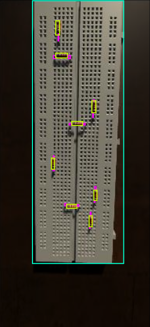
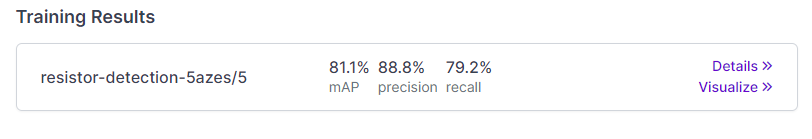
The final dataset has around 250 real images of resistors, wires, and breadboards. It has 500 fully annotated synthetically generated images of random circuits on random table backgrounds with random lighting and a random camera angle. The training results were excellent considering the synthetic data is all computer generated.
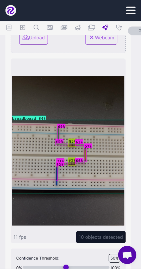
Synthetic data provides a cheap and fast way to attain massive datasets with perfectly annotated images. It helped me avoid intricately labeling small circuit components. Some possible next steps with the project include: identifying more circuit components, integrating the model into a mobile app, and detecting the value of the resistors.
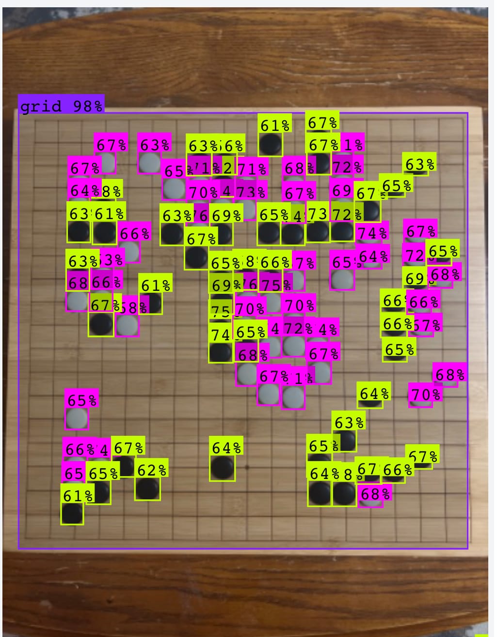
Bonus Project: Synthetic Data for Go Positions
Using the same method, I created a fully synthetic dataset of go positions.
Cite this Post
Use the following entry to cite this post in your research:
James Gallagher. (Mar 23, 2023). How I Used Synthetic Data with Unity Perception to Minimize Annotation Time. Roboflow Blog: https://blog.roboflow.com/synthetic-data-breadboards/