
Weld quality is a cornerstone of structural integrity in industries ranging from aerospace to automotive manufacturing. A single microscopic crack or an instance of porosity can lead to catastrophic failure, making rigorous inspection a non-negotiable part of the production cycle. Historically, this has relied on manual spot-checks, which are subject to human fatigue and the high speed of modern assembly lines.
Today, computer vision is transforming industrial quality control. By implementing an automated, high-precision inspection system, manufacturers can achieve 100% inspection coverage with consistent, objective results.
In this guide, we will walk through building a simple object detection system designed to identify weld defects in real-time. We will use a multi-layered approach: a high-speed RF-DETR model to locate welds and a Gemini multimodal model to perform deep reasoning on the results.
The Role of Computer Vision in Industrial Welding
Manual weld inspection is often a bottleneck in high-throughput environments. Automated machine vision systems provide a scalable solution that monitors production lines 24/7.
1. Defect Identification
Modern models can be trained to distinguish between critical classes:
- Good_Welding: A clean, structurally sound join.
- Bad_Welding: General structural failure or poor fusion.
- Crack: Linear fractures that compromise the metal's strength.
- Porosity: Small gas pockets or holes within the weld.
- Spatters: Droplets of molten material that have solidified on the surface.
- Excess_Reinforcement: Too much weld metal, leading to stress concentrations.
2. Real-Time Feedback
By deploying models at the edge, systems can trigger immediate rejection mechanisms or alert human operators the moment a defect is detected, preventing faulty parts from moving further down the line.
The AI Solution: A Two-Layer Inspection Agent
To maximize both speed and accuracy, we will build a system that splits the workload into two specialized roles.
- Stage 1: The Detector (Perception Layer): We use a custom-trained RF-DETR model. This is the first real-time transformer-based detector to exceed 60 mAP, making it ideal for the precision required in manufacturing. Its job is to find the weld and provide an initial classification.
- Stage 2: The Inspector (Reasoning Layer): We integrate Gemini via Roboflow Workflows. This serves as the "brain" that analyzes the sections provided by the detector to verify the defect and provide a detailed explanation of the failure mode.
If you’d rather follow along visually, this video walks through the full process, from cloning the dataset in Roboflow Universe to training a custom detection model.
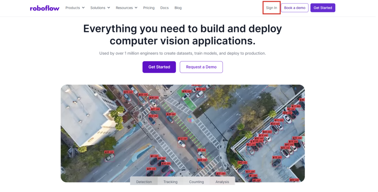
Step 1: Log into Roboflow
Navigate to Roboflow and sign in to your workspace. If you are new to the platform, you can sign up for free to access the suite of annotation and training tools.
Ensure you have a workspace set up for your projects.
Step 2: Source a Weld Defect Dataset from Universe
The quality of your vision system depends on your data. Roboflow Universe hosts over 500,000 open-source datasets.
Search for "Weld Quality" or "Metal Defects" on Universe.
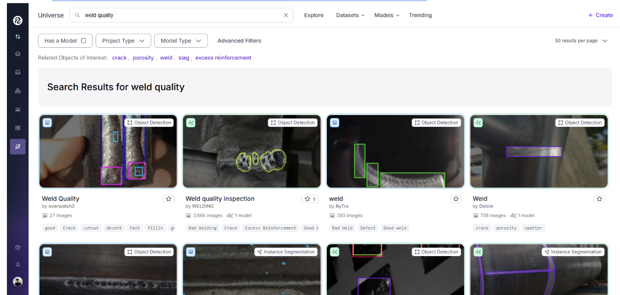
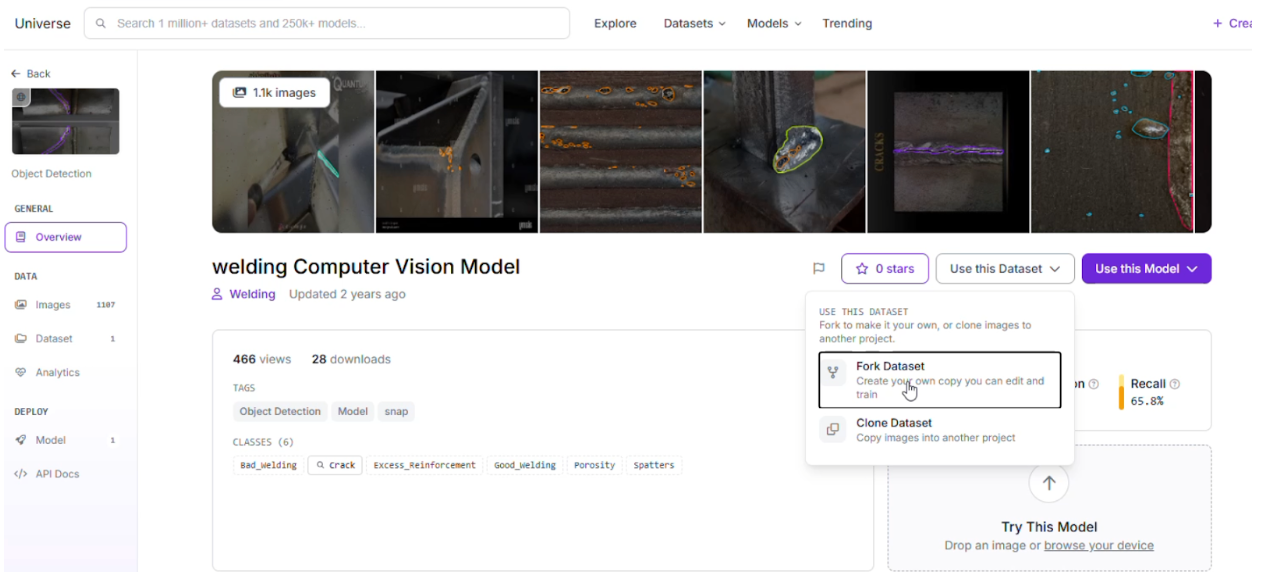
For this project, we recommend the Weld Quality Inspection dataset.
Click "Fork Project" to bring the images and existing labels into your own workspace for customization.
Step 3: Labeling and Annotation
If you want to add more images, simply use Roboflow’s annotation tools to separate the images into classes and then use them in the dataset.
Step 4: Apply Preprocessing and Augmentations
To ensure your system works under varying factory lighting and camera angles, apply the following steps in the Dataset tab:
Preprocessing:
- Auto-Orient: Applied to ensure images are correctly rotated regardless of camera orientation.
- Resize: Stretch to 512x512. This standardizes input sizes for optimal inference speed.
- Grayscale: Applied to help the model focus on texture and shape rather than color reflections on the metal.
Augmentations (Outputs per training example: 2):
- Saturation: Between -25% and +25% (handles varying metallic sheen).
- Brightness: Between -15% and +15% (simulates different factory lighting).
- Exposure: Between -10% and +10% (accounts for camera flash or external glares).
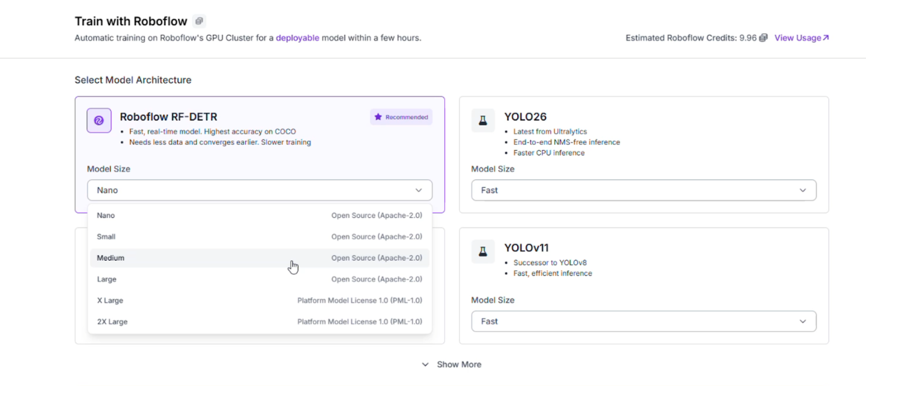
Step 5: Train the RF-DETR Model
With your data prepared, it is time to train the "eyes" of your system. RF-DETR (Roboflow Detection Transformer) provides the stability of a transformer with the speed of a traditional detector.
Go to the "Train" tab and select Train Model.
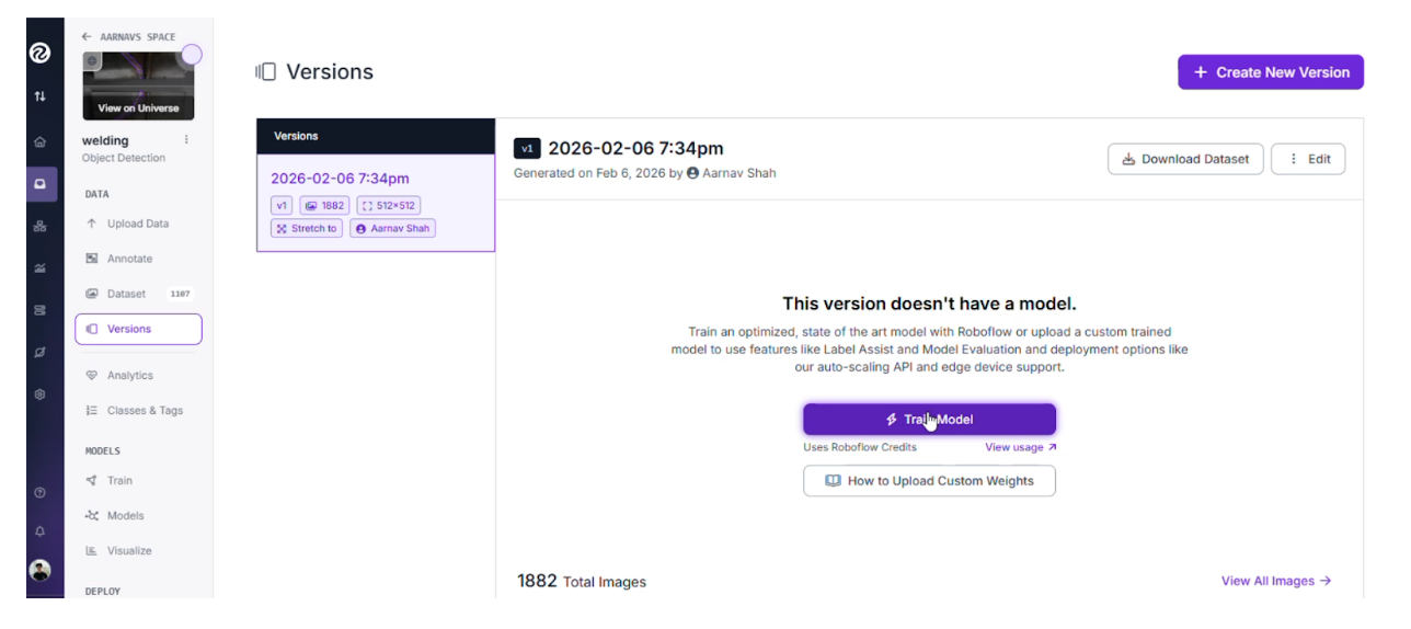
Choose the RF-DETR architecture.
Once training is complete, review the Confusion Matrix to ensure the model accurately distinguishes between similar defects like Porosity and Spatters.
Step 6: Build the Multimodal Workflow
We will now connect our RF-DETR model to Gemini using a low-code interface to create a robust vision agent. Here's the workflow we're building.
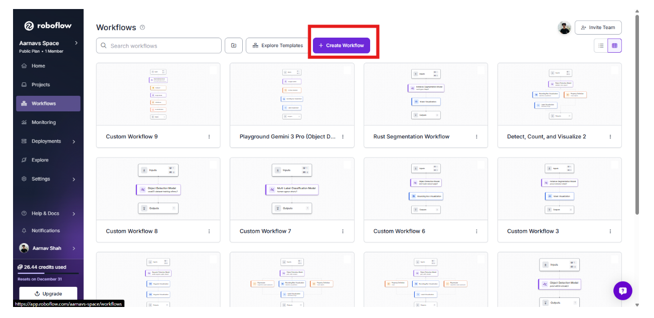
1. Initialize the Workflow
Create a new workflow in the Workflows tab and click “build your own”. This acts as the central logic for your edge system.
2. Add the RF-DETR Perception Layer
Add an Object Detection Model block and select your trained weld inspection model. This block will output bounding boxes for our six classes: Bad_Welding, Crack, Excess_Reinforcement, Good_Welding, Porosity, and Spatters.
3. Gate the Logic with a Condition
Add a Continue If block. This will check the detections and continue only if there are zero detections labelled Good_Welding with confidence ≥ 0.8.
If even one high-confidence Good_Welding detection exists, the pipeline should stop.
In short: proceed only when good welding is NOT confidently detected. This ensures we only use the reasoning layer when a potential issue is spotted.
4. Add the Reasoning Layer: Gemini
Add a Google Gemini block. This multimodal model will act as the "second opinion."
- Task Type: Structured Output Generation.
- Prompt:
{
  "good_welding_confidence": "Report the highest confidence score for the Good_Welding class if detected; otherwise return null",
  "primary_issue_detected": "Name the most critical defect detected, or describe the main uncertainty if confidence is low (use 'None' if the weld is clearly acceptable)",
  "suggested_focus_area": "Identify the welding parameter most likely responsible for the issue (e.g., heat input, travel speed, electrode angle, shielding gas, surface preparation)",
  "ai_task_prompt": "Briefly explain the likely cause of the issue and provide specific, actionable steps to improve weld quality"
}
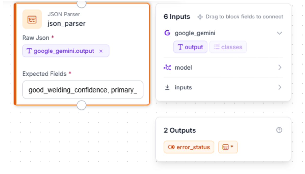
5. Add a JSON Parser
To allow users to retrieve/view information clearly, we can add a JSON parser.
This block takes Gemini’s natural-language reasoning and converts it into a structured, machine-readable format. Define the expected fields: good_welding_confidence, primary_issue_detected, suggested_focus_area, ai_task_prompt
Step 7: Test and Deploy to the Edge
Use the "Run Preview" button in the Workflow editor to upload images of welds and see the multi-layered logic in action.
- Success Scenario: RF-DETR identifies a Crack -> Gemini confirms the linear fracture and suggests a re-weld -> The system flags the part.
Image Used:
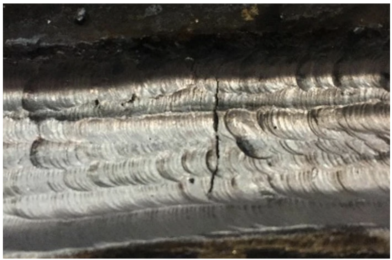
Example Output:
"google_gemini": {
      "good_welding_confidence": null,
      "primary_issue_detected": "Centerline Cracking (Hot Cracking)",
      "suggested_focus_area": "Heat Input / Joint Design / Travel Speed",
      "ai_task_prompt": "The prominent vertical crack running down the center of the weld bead suggests solidification cracking, often caused by high restraint or excessive heat input leading to a deep, narrow bead profile. To fix this, increase travel speed slightly to widen the bead, ensure the depth-to-width ratio is not excessive (keep it near 1:1), and verify that fit-up is not causing excessive stress on the cooling puddle.",
"error_status": false- Refinement Scenario: RF-DETR sees Spatters -> Gemini determines they are within tolerance limits -> The system allows the part to pass.
Once validated, you can deploy this workflow to an edge device, such as an NVIDIA Jetson, to run locally on your production line.
Conclusion: Detect Bad Welds with Computer Vision
Building an automated weld inspection system allows manufacturers to move beyond manual spot-checks and embrace a data-driven approach to quality. By combining the raw speed of RF-DETR with the visual reasoning of Gemini, you create a vision agent that is both fast and incredibly precise.
Ready to secure your production line? Start building by exploring weld datasets on Universe or sign up for a Roboflow account today.
Written by Aarnav Shah
Cite this Post
Use the following entry to cite this post in your research:
Contributing Writer. (Feb 10, 2026). How to Build an Edge Vision System for Weld Inspection. Roboflow Blog: https://blog.roboflow.com/vision-system-for-weld-inspection/