
Smart homes are becoming more intelligent every day, with automation tools that make life safer and more convenient.
You can combine computer vision, mobile, and IoT technologies to build complex applications that use real-world visual cues to control a device. For example, you could build an application that monitors doors and closes them if they remain open for too long.
Using Roboflow, you can quickly build and train a custom dataset of doors in different states (open, closed, partially open).
Then, with CoreML models running natively on iOS, you can integrate real-time detection into an app that monitors your doors through a camera feed.
Combined with a simple servo system, this detection can trigger an automated closing mechanism, helping keep your space secure and hassle-free. Here is an example of this system in action:
In this blog post, we are going to walk through how to build a system that automatically closes doors that have been left open using computer vision.
We will:
- Collect data to train a computer vision model that identifies doors. We will do this with a custom mini iOS app we will make for the purpose of data collection.
- Train a model to identify doors.
- Run our model in an iOS application with CoreML.
- Connect our model to the real-world using a Swift ESP32 interface.
- Trigger a linear actuator when a message is received from our application.
Let's get started!
Create a Temporary App to Collect Data and Train a Door Detection Model
As we'll be detecting if a door is open or closed from a mobile app, we'll need to train a model to do this. If you haven't made an iOS app before, refer to this guide showing how to use Roboflow to build a vision app on iOS for setting up Xcode and installing the necessary dependencies.
Additionally, you can clone this version of the app through Github, making replicating the code easier.
In your project, navigate to ContentView.swift. This code builds a temporary homepage collect training images of doors by using the device camera, automatically capturing and saving photos at set intervals with a progress counter. It includes UI controls for starting/stopping data collection, managing settings like maximum image count, and displaying capture status in real time.
Next, navigated to a file called CameraPreviewView.swift:
import SwiftUI
import AVFoundation

struct CameraPreviewView: UIViewRepresentable {
    let cameraManager: CameraManager

    func makeUIView(context: Context) -> UIView {
        let view = UIView(frame: UIScreen.main.bounds)

        let previewLayer = cameraManager.getPreviewLayer()
        previewLayer.frame = view.frame
        view.layer.addSublayer(previewLayer)

        return view
    }
}
This CameraPreviewView struct wraps an AVCaptureVideoPreviewLayer inside SwiftUI, letting you display a live camera feed in your app’s UI. It uses UIViewRepresentable to bridge UIKit’s camera preview layer into SwiftUI. Next, to manage taking photos, theres another file called CameraManager.swift.
CameraManager manages the iOS camera by configuring an AVCaptureSession, starting/stopping the feed, and capturing photos. It publishes the live state, captured images, and errors so SwiftUI views like ContentView can react to camera events.
Additionally, before saving the images, we're going to run a compression alg as well as convert images to greyscale, just so that training is faster and easier. Check out ImageProcessor.swift.
Finally, to save the images, another file called ImageSaver.swift saves the images with the PHPhotolibrary:
import UIKit
import Photos
class ImageSaver: NSObject, ObservableObject {
@Published var isSaving = false
@Published var saveStatus = ""
@Published var imagesSaved = 0
func saveImage(_ image: UIImage) {
DispatchQueue.main.async {
self.isSaving = true
self.saveStatus = "Saving image..."
}
PHPhotoLibrary.requestAuthorization { [weak self] status in
DispatchQueue.main.async {
if status == .authorized {
self?.performSave(image)
} else {
self?.isSaving = false
self?.saveStatus = "Photo library access denied"
}
}
}
}
private func performSave(_ image: UIImage) {
PHPhotoLibrary.shared().performChanges({
PHAssetChangeRequest.creationRequestForAsset(from: image)
}) { [weak self] success, error in
DispatchQueue.main.async {
self?.isSaving = false
if success {
self?.imagesSaved += 1
self?.saveStatus = "Saved \(self?.imagesSaved ?? 0) images"
} else {
self?.saveStatus = "Failed to save: \(error?.localizedDescription ?? "Unknown error")"
}
}
}
}
func resetCounter() {
imagesSaved = 0
saveStatus = ""
}
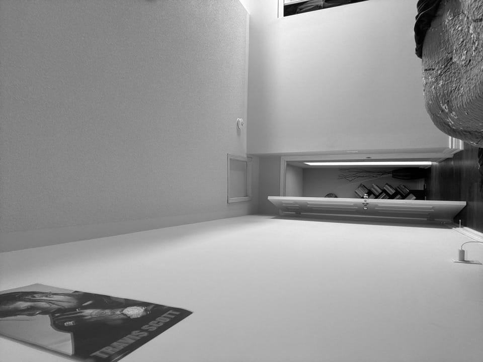
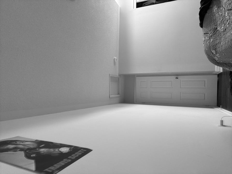
}From here, build and run the app in Xcode on an iPhone to be able to set it up and collect data. Here are some sample images post-compression and greyscale.
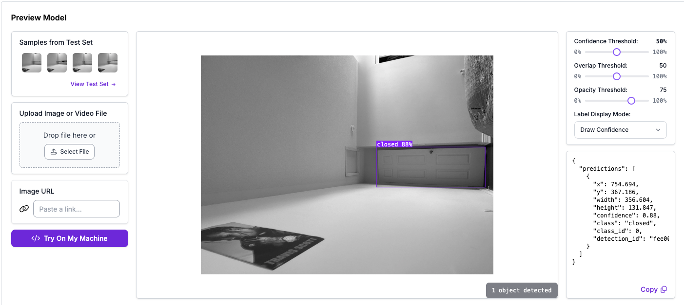
Finally, upload these images and train an object detection model to recognize "open" and "closed classes for these pictures of a door.
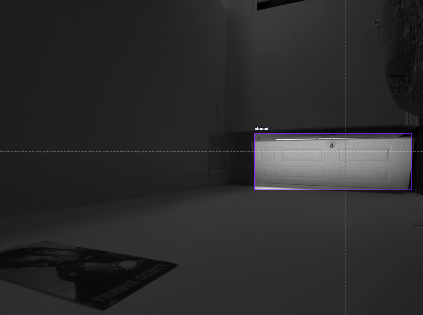
Once it's been trained, you can check how well it performs in the model evalutation:
Now, we're ready to build the actual app!
Create an App that Takes Photos and Performs Inference and Connects to an ESP32
Refer to the latest app version on Github and clone it.
To use Roboflow in our app, create 2 new files are added: RoboflowConfig.swift and RoboflowManager.swift. The config file stores all of the necessary information for our model and project, such as API keys and the model name and version. Here is an example:
import Foundation

struct RoboflowConfig {
    // Replace these values with your actual Roboflow credentials
    static let apiKey = "API KEY"
    static let modelName = "MODEL NAME"
    static let modelVersion = 2

    // Detection parameters - adjust these based on your model's needs
    static let confidenceThreshold: Float = 0.5
    static let overlapThreshold: Float = 0.5
    static let maxObjects = 1
}
In RoboflowManager.swift, we use this info to load the model as a CoreML model to run on iOS, and prepare it for running on photos taken by the app. Then, once RoboflowManager makes a prediction, it uses the NetworkManager object to send an event to an ESP32 (we will later implement this on the board).
The NetworkManager object is located in NetworkManager.swift. It keeps track of the ESP32 port and IP, allowing for easy client connection. The port that we set will later be the same port that we set up in the actual ESP32. Additionally, make sure to change the IP address to the IP address of your ESP32.
Additionally, ContentView.swift was updated to include RoboflowManager and actually make predictions.
Now, after building and running:
Next, let's connect the app to the ESP32 and wire it up to close the door!
Wirelessly Connect ESP32 to Receive Events
For programming the ESP32, we'll be using the Arduino IDE, and I suggest following this guide walking through the set up for using it on ESP32 development modules. Additionally, some other parts you'll need are: a 12V, 8 in. stroke linear actuator, a L298N motor driver, and a 12V power supply with a DC output jack.
If you're waiting on shipments for these parts, you can set up the ESP32 logic right away, and wire everything up after!
To do this, create a new ESP32 project in the Arduino IDE and add the following to the sketch (.ino file):
/*
 Door Controller WiFi Server with L298N

 A simple web server that receives door state events from the iOS app.
 When the app detects an open door, it sends a GET request to /open
 and the ESP32 activates the linear actuator to close the door.

 Circuit:
 * ESP32 connected to WiFi
 * L298N H-Bridge with linear actuator
 * ESP32 Pin 25 → L298N IN1
 * ESP32 Pin 26 → L298N IN2

 */

 #include <WiFi.h>

 const char *ssid = "Your WiFi name";
 const char *password = "Your WiFi password";

 WiFiServer server(80);

 // L298N H-Bridge pins
 const int IN1_PIN = 25;  // L298N IN1 (Forward/Extend)
 const int IN2_PIN = 26;  // L298N IN2 (Reverse/Retract)

 // Linear actuator control variables
 unsigned long lastActuatorUpdate = 0;
 bool isDoorClosing = false;
 bool extending = false;  // true when extending, false when retracting
 unsigned long doorCloseStartTime = 0;
 bool isInitialized = false;  // Track if actuator has been initialized
 unsigned long initStartTime = 0;  // Track initialization start time

 void setup() {
   Serial.begin(115200);

   // Set up L298N pins
   pinMode(IN1_PIN, OUTPUT);
   pinMode(IN2_PIN, OUTPUT);

   // Stop actuator initially
   digitalWrite(IN1_PIN, LOW);
   digitalWrite(IN2_PIN, LOW);

   Serial.println("L298N H-Bridge initialized");

   delay(10);

   // We start by connecting to a WiFi network
   Serial.println();
   Serial.println();
   Serial.print("Connecting to ");
   Serial.println(ssid);

   WiFi.begin(ssid, password);

   while (WiFi.status() != WL_CONNECTED) {
     delay(500);
     Serial.print(".");
   }

   Serial.println("");
   Serial.println("WiFi connected.");
   Serial.println("IP address: ");
   Serial.println(WiFi.localIP());

   server.begin();
   Serial.println("Door controller server started!");

   // Start initialization sequence - retract for 23 seconds to ensure starting position
   isInitialized = false;
   initStartTime = millis();
   digitalWrite(IN1_PIN, LOW);
   digitalWrite(IN2_PIN, HIGH);  // Start retracting
   Serial.println("Initializing: RETRACTING actuator to known position (23 seconds)...");
 }

 void loop() {
   // Handle initialization sequence first
   if (!isInitialized) {
     unsigned long currentTime = millis();
     unsigned long elapsed = currentTime - initStartTime;

     // Keep extending during initialization (to retract the actuator)
     digitalWrite(IN1_PIN, HIGH);  // Extend to retract actuator
     digitalWrite(IN2_PIN, LOW);

     if (elapsed >= 23000) {  // 23 seconds initialization
       // Stop actuator and mark as initialized
       digitalWrite(IN1_PIN, LOW);
       digitalWrite(IN2_PIN, LOW);
       isInitialized = true;
       Serial.println("Initialization complete - Actuator in retracted position");
       Serial.println("Ready to receive door events!");
     }
     return;  // Don't process door events during initialization
   }

   WiFiClient client = server.accept();  // listen for incoming clients

   if (client) {                     // if you get a client,
     Serial.println("New Client.");  // print a message out the serial port
     String currentLine = "";        // make a String to hold incoming data from the client
     while (client.connected()) {    // loop while the client's connected
       if (client.available()) {     // if there's bytes to read from the client,
         char c = client.read();     // read a byte, then
         Serial.write(c);            // print it out the serial monitor
         if (c == '\n') {            // if the byte is a newline character

           // if the current line is blank, you got two newline characters in a row.
           // that's the end of the client HTTP request, so send a response:
           if (currentLine.length() == 0) {
             // HTTP headers always start with a response code (e.g. HTTP/1.1 200 OK)
             // and a content-type so the client knows what's coming, then a blank line:
             client.println("HTTP/1.1 200 OK");
             client.println("Content-type:text/html");
             client.println();

             // the content of the HTTP response follows the header:
             client.print("Door Controller Ready<br>");
             client.print("Send GET /open to indicate door is open<br>");
             client.print("Send GET /closed to indicate door is closed<br>");

             // The HTTP response ends with another blank line:
             client.println();
             // break out of the while loop:
             break;
           } else {  // if you got a newline, then clear currentLine:
             currentLine = "";
           }
         } else if (c != '\r') {  // if you got anything else but a carriage return character,
           currentLine += c;      // add it to the end of the currentLine
         }

         // Check to see if the client request was "GET /open" or "GET /closed":
         if (currentLine.endsWith("GET /open")) {
           Serial.println("open");
           Serial.println("Door is OPEN! Activating linear actuator...");
           startDoorClosing();
         }
         if (currentLine.endsWith("GET /closed")) {
           Serial.println("Door is CLOSED");
         }
       }
     }
     // close the connection:
     client.stop();
     Serial.println("Client Disconnected.");
   }

   // Linear actuator control - runs when door needs to be closed
   controlLinearActuator();
 }


 void startDoorClosing() {
   if (!isInitialized) {
     Serial.println("Cannot start door closing - actuator not yet initialized");
     return;
   }

   if (isDoorClosing) return;  // Prevent multiple activations

   isDoorClosing = true;
   extending = true;
   doorCloseStartTime = millis();
   Serial.println("Starting linear actuator: EXTENDING to close door");
 }

 void controlLinearActuator() {
   if (!isDoorClosing) return;

   unsigned long currentTime = millis();
   unsigned long elapsed = currentTime - doorCloseStartTime;

   if (extending) {
     // Retract for 20 seconds to fully push door closed (200mm stroke)
     digitalWrite(IN1_PIN, LOW);  // Retract to close door
     digitalWrite(IN2_PIN, HIGH);

     if (elapsed >= 20000) {  // 20 seconds for full 200mm retraction
       extending = false;
       doorCloseStartTime = currentTime;  // Reset timer for extend phase
       Serial.println("Linear actuator: EXTENDING back to neutral (20 seconds)");
     }
   } else {
     // Extend for 20 seconds to fully return to neutral position
     digitalWrite(IN1_PIN, HIGH);  // Extend to return to neutral
     digitalWrite(IN2_PIN, LOW);

     if (elapsed >= 20000) {  // 20 seconds for full 200mm extension
       // Stop actuator and end sequence
       digitalWrite(IN1_PIN, LOW);
       digitalWrite(IN2_PIN, LOW);
       isDoorClosing = false;
       Serial.println("Door closing sequence complete - actuator stopped");
       Serial.println("Total cycle time: 40 seconds");
     }
   }
 }
This ESP32 program hosts a WiFi server that listens for /open or /closed requests from the iOS app. When /open is received, it drives the linear actuator through the L298N to push the door shut, then returns the actuator to a neutral position.
Upload this sketch to your ESP32. Now we're ready to wire everything up!
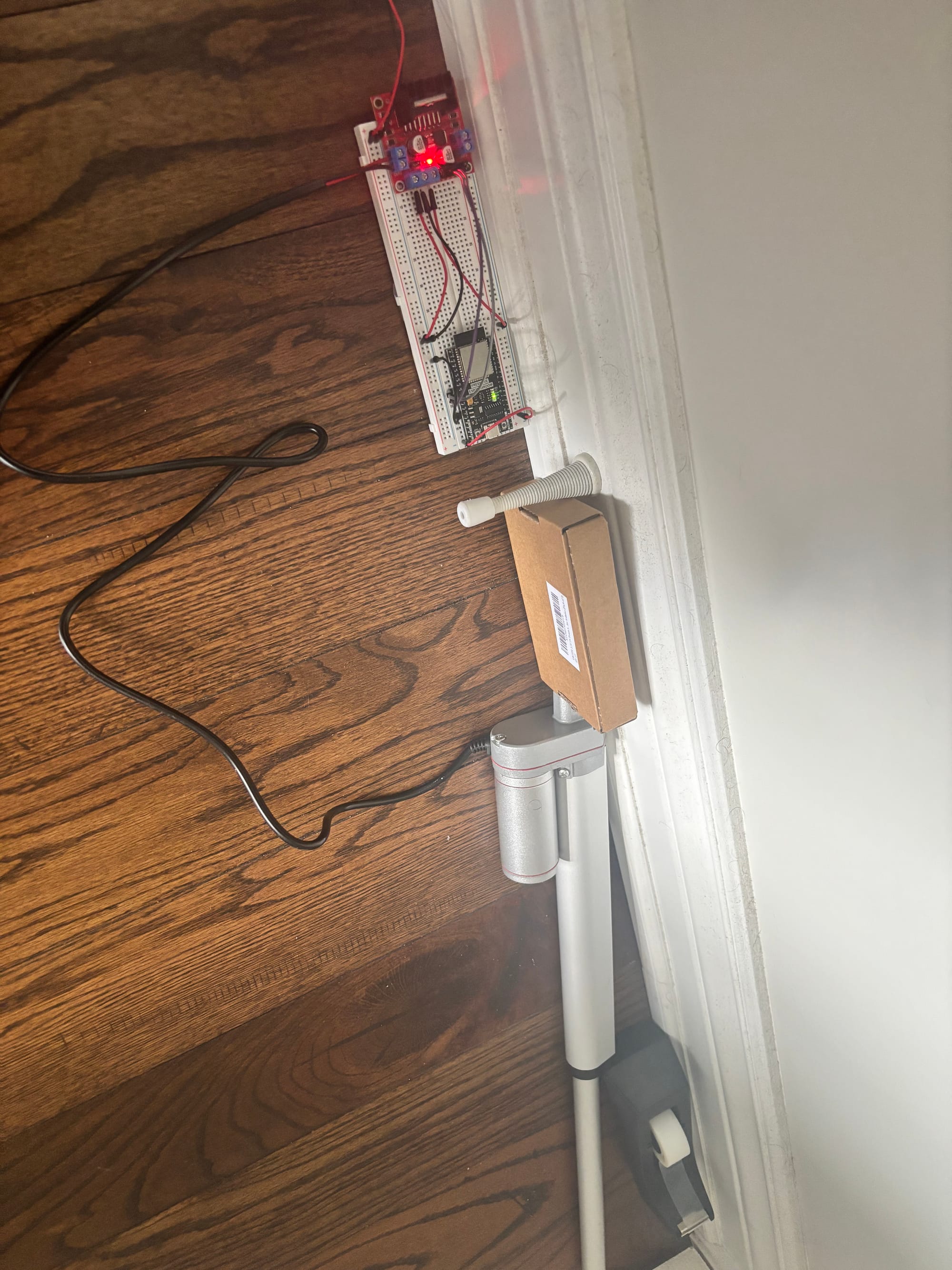
Circuitry for Automatically Closing Door
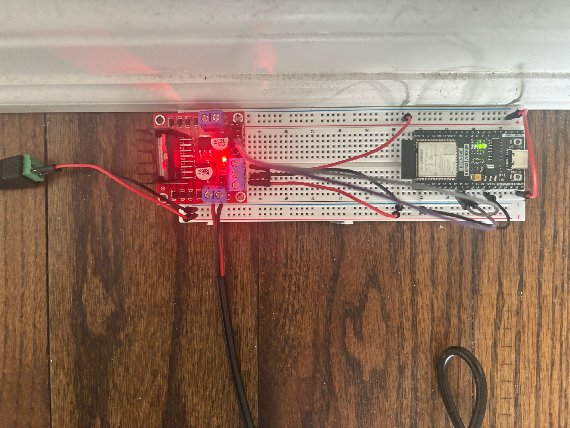
From the PSU, you'll need to connect the DC jack and connect jumper wires to a set of + and - rails on the breadboard. These 2 rails will be used to provide power to the linear actuator. Do NOT power your linear actuator directly from the ESP32, this could potentially fry your components due to the excess voltage.
After that, connect a jumper cable from the 12V rail to the 12V port on the L298N, the ground rail to the ground port, and then connect the red and black wires from the actuator to OUT1 and OUT2 on the L298N respectively. From there, connect pins 25 and 26 to INP1 AND INP2 on the L298N, and connect the 5v port on the L298N to a positive rail on the breadboard. Then, to the same rail, connect the 5v pin on the ESP32, and finally connect the ground pin on the ESP32 to the ground rail (first one, from the PSU).
That was a lot, but heres a visual to guide you:
And with that, all of the hardware/software components are complete! Now, to get it to open and close, set up your actuator in a way that is unobstructed by other object and will allow you to close the door fully.

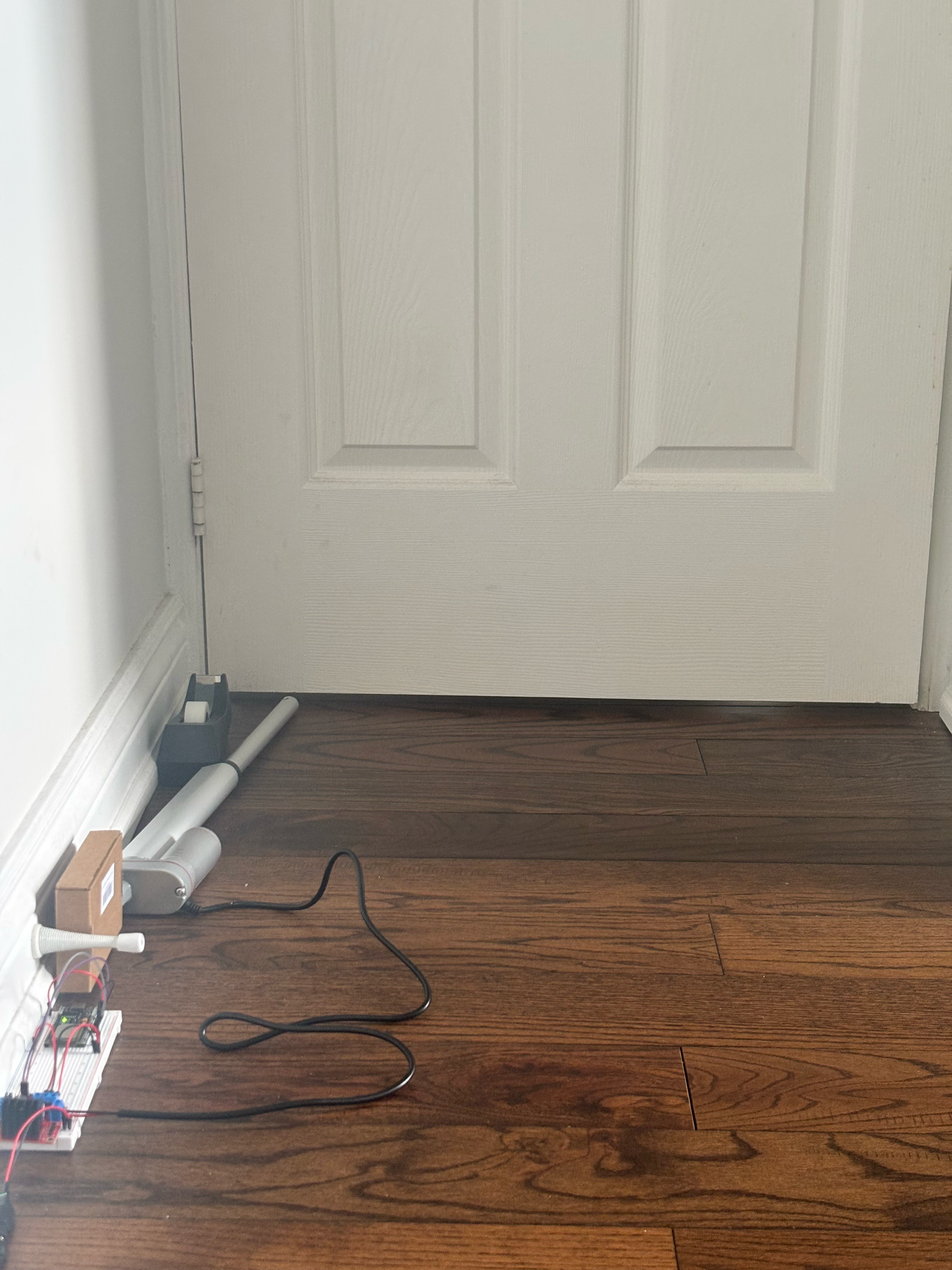
Finally, our door closer is complete!
Conclusion
Congratulations on successfully making an automated door closing tool with iOS CoreML and ESP32 hardware! If you have any questions about this project, check out the Github repositories: iOS App, ESP32.
Cite this Post
Use the following entry to cite this post in your research:
Aryan Vasudevan. (Aug 25, 2025). How to Use Roboflow CoreML Models and ESP32 Hardware for IoT. Roboflow Blog: https://blog.roboflow.com/coreml-esp32-iot-vision/