
This tutorial builds a computer vision pipeline that detects hand gestures from a camera feed and uses those detections to control the state and brightness of an AC light bulb over MQTT. An object detection model is trained on a labeled gesture dataset using Roboflow, and inference results are published to an MQTT broker that an Arduino-based firmware node subscribes to for executing bulb commands. The dataset for this project is available on Roboflow Universe, and the full code is on GitHub.
In this blog post, we will walk through how to build a hand gesture-based light control system using computer vision. This system offers a unique way to control the lighting in the home environment with simple hand gestures. With the help of specific hand gestures, users can effortlessly adjust the brightness or turn lights on and off without the need for switches or remote controls.
Here is a demo of the system detecting hand gestures which we use to determine which control message to send to a light. Messages are sent over MQTT.

Without further ado, let's get started!
How the Project Works
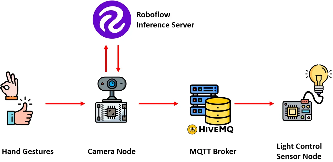
The system operates by using a camera-based node to capture hand gestures performed by the user. These captured images are then processed by a computer vision model, which has been trained using Roboflow. This model is specifically designed to recognize predefined hand gestures corresponding to distinct tasks, such as turning the light on, off, or adjusting brightness levels. For this project, a object detection model was trained.
The computer vision model receives the input from a camera-based node and identifies a specific gesture in the image. The model then communicates the result to a camera-based node, which in turn transmits this information to a remote MQTT broker. This MQTT broker serves as a communication hub, facilitating the exchange of messages between different nodes within the system.
On the receiving end, another sensor node responsible for controlling the AC light bulb receives the message indicating the detected gesture from the MQTT broker. Based on the information received, this sensor node executes the necessary actions to adjust the state or brightness level of the AC light bulb. The following image shows the structure of the system.
How the System is Developed
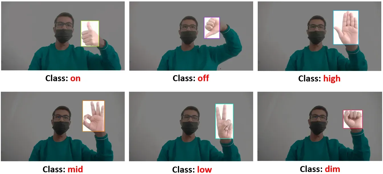
To facilitate the detection of various hand gestures for controlling the AC light bulb, we will train an object detection model. This model will be trained to recognize different hand gestures, each corresponding to distinct operations or commands, including turning the bulb on and off, as well as adjusting the brightness level. The following table shows the gesture and corresponding operation it will be used to perform.


Here are the steps used to develop the system:
- Collect and label a dataset
- Train an object detection model
- Detect hand gestures and send result over MQTT
- Building firmware to control light bulb
Step #1: Collect and Label a Dataset
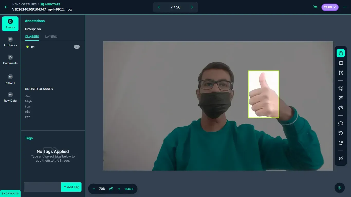
The dataset containing images of hand gestures, depicting a range of hand actions, was manually collected and then uploaded to the Roboflow platform for labeling.
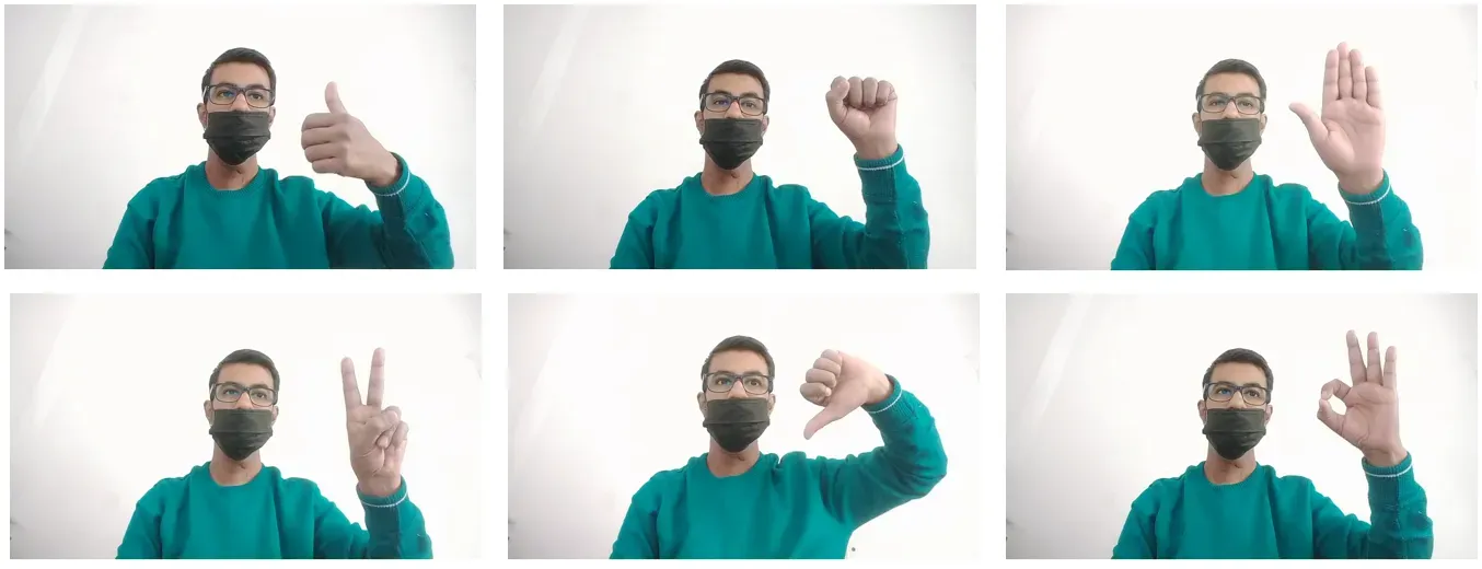
Bounding boxes have been applied to label each image, distinguishing between six classes: 'on', 'off', 'high', 'mid', 'low', and 'dim', respectively.
Step #2: Train an Object Detection Model
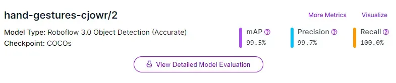
After completing the labeling process, a version of the dataset is generated, and the model is trained using the Roboflow auto-training option. The training accuracy achieved is 99.5%.
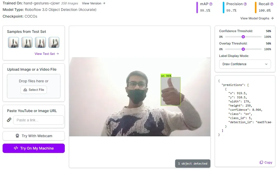
Upon completion of training, the model is automatically deployed to a cloud API. Roboflow provides various options for testing and deploying the model, including live testing in a web browser and deployment to edge devices. The following image demonstrates the model being tested using the Roboflow web interface.
Step #3: Detect hand gestures and send result over MQTT
To detect hand gestures, we will build a JavaScript application that uses our vision model. This app runs in a web browser and captures the user’s hand gestures using a webcam. The app communicates with the computer vision model using the Robfolow cloud API.
Our model detects the hand gesture and sends the result about the detected gesture to an MQTT broker on lightcmd topic. The message published by this JavaScript app will be used by NodeMCU based client device to control the light bulb. For building the JavaScript App, I have used roboflow.js library from this post.
I have updated the code from hand-detector model from this post to connect it to MQTT broker and send the result from prediction.class to the MQTT topic lightcmd.
client = new Paho.MQTT.Client("broker.hivemq.com", 8000 ,"light-cmd-publisher-1");
client.connect();

// Previous Code...

var publishable_key = "KEY";
    var toLoad = {
        model: "hand-gestures-cjowr",
        version: 2
    };

// Previous Code...

const renderPredictions = function (predictions) {

// Previous Code...

predictions.forEach(function (prediction) {
            const x = prediction.bbox.x;
            const y = prediction.bbox.y;

            const width = prediction.bbox.width;
            const height = prediction.bbox.height;

            // Draw the text last to ensure it's on top.
            ctx.font = font;
            ctx.textBaseline = "top";
            ctx.fillStyle = "#000000";
            ctx.fillText(
                prediction.class,
                (x - width / 2) / scale + 4,
                (y - height / 2) / scale + 1
            );

            console.log(prediction.class);
            message = new Paho.MQTT.Message(prediction.class.toString());
            message.destinationName = "lightcmd";
            client.send(message);
        });
};
Above, replace KEY with your Roboflow publishable key.
With our code ready, we can start configuring the firmware for our project. This Arduino based firmware will be uploaded to our NodeMCU based device.
Step #4: Configuring Firmware
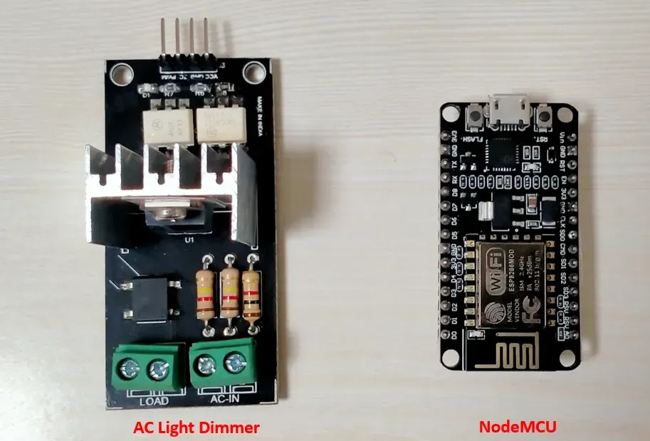
In this section we will learn how to build firmware to control a light bulbs. First, we need the following hardware components.
- NodeMCU
- AC Light dimmer Module
- Wires
- Bulb Holder
- Bulb
The NodeMCU is the brain of the device which will execute firmware code and AC Light dimmer Module will be used to control the alternating current (AC) voltage.
AC Light Dimmer Module controls the brightness of the AC bulb. The following diagram shows how to connect all components of the system.
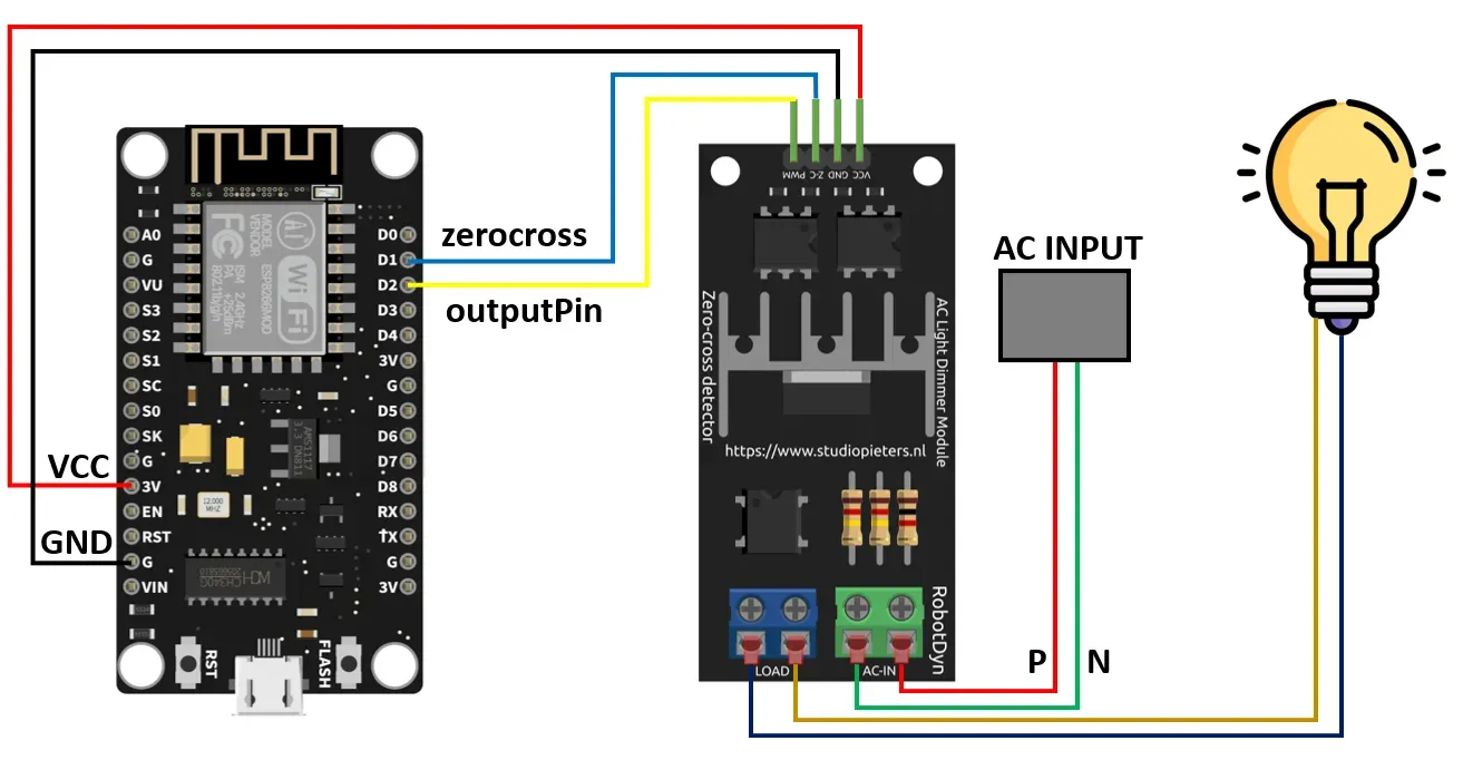
To regulate the AC bulb, we need the RBDDimmer library for Arduino from RobotDyn. We utilize following functions from this library to control the AC light bulb.
void setState(ON_OFF_typedef ON_OFF)
The setState() function is used to turn On or OFF the light bulb.
void setPower(int power);
The setPower() function is used to set the brightness level of light bulb. The values can be between 0% to 100%.
To enable MQTT messaging, we require another client library named PubSubClient. You can easily install this library using the Library Manager in the Arduino IDE. Before building the firmware, it's essential to include the necessary libraries.
#include <ESP8266WiFi.h>
#include "PubSubClient.h"
#include "RBDdimmer.h"
Define the data pin number on which the dimmer module is connected.
#define zerocross D1
#define outputPin D2

Setup WiFi and MQTT broker details
const char* ssid = "WIFI_SSID";
const char* password =  "WIFI_PASSWORD";
const char* mqttServer = "broker.hivemq.com";
int port = 1883;
Next, we can initialize WiFi, the MQTT client, and the dimmer object:
WiFiClient espClient;
PubSubClient client(espClient);
dimmerLamp dimmer(outputPin, zerocross);
Next, override the callback function to subscribe to the MQTT topic, read incoming messages, and control the light bulb accordingly.
void callback(char* topic, byte* payload, unsigned int length) {
    String command = "";

    for (int i = 0; i < length; i++) {
      command += (char)payload[i];
   }

   static String previousCommand = "";

  if (command != previousCommand) {

    Serial.print("Message arrived in topic: ");
    Serial.println(topic);
    Serial.print("Message:");

    if (strcmp(command.c_str(), "on") == 0) {
        Serial.println(command);
        dimmer.setState(ON);
    } else if (strcmp(command.c_str(), "off") == 0) {
        Serial.println(command);
        dimmer.setState(OFF);
    } else if (strcmp(command.c_str(), "high") == 0) {
        Serial.println(command);
        dimmer.setPower(100);
        Serial.println("Brightness set to 100%");
    } else if (strcmp(command.c_str(), "mid") == 0) {
        Serial.println(command);
        dimmer.setPower(75);
        Serial.println("Brightness set to 75%");
    } else if (strcmp(command.c_str(), "low") == 0) {
        Serial.println(command);
        dimmer.setPower(50);
        Serial.println("Brightness set to 50%");
    } else if (strcmp(command.c_str(), "dim") == 0) {
        Serial.println(command);
        dimmer.setPower(25);
        Serial.println("Brightness set to 25%");
    }
    previousCommand = command;
  }
}
In the setup function, our first step is connecting to the WiFi network, followed by establishing a connection to the MQTT broker. Once connected to the broker, the device subscribes to the MQTT topic lightcmd and becomes ready to receive messages.
void setup() {

  Serial.begin(115200);
  WiFi.begin(ssid, password);

  while (WiFi.status() != WL_CONNECTED) {
    delay(500);
    Serial.println("Connecting to WiFi..");
  }
  Serial.println("Connected to the WiFi network");

  client.setServer(mqttServer, mqttPort);
  client.setCallback(callback);

  while (!client.connected()) {
    Serial.println("Connecting to MQTT...");

    if (client.connect("lightcontrol-001" )) {

      Serial.println("connected");

    } else {

      Serial.print("failed with state ");
      Serial.print(client.state());
      delay(2000);

    }
  }
   client.subscribe("lightcmd");
}
In the graphic below, the output of the JavaScript app (on the right) is displayed, detecting hand gestures, while the Arduino firmware running on the device (on the left) controls the state and brightness of the light bulb.
Conclusion
In this project we have implemented a computer vision pipeline to control AC light bulb. Similar techniques can also be implemented for other types of appliances.
With the help of object detection results from our computer vision model, the project accurately extracts information about the hand gestures and publishes the results of the detected hand gesture to MQTT topic on an MQTT broker over the internet. The Arduino based firmware is used to control the state and brightness of AC bulb based on the object detection results for hand gesture.
All code for this project is available at GitHub. The dataset used for this project is available on Roboflow Universe.
Cite this Post
Use the following entry to cite this post in your research:
Timothy M. (Mar 26, 2024). Build a Gesture-Based Light Controller with Computer Vision. Roboflow Blog: https://blog.roboflow.com/gesture-light-system/