
Image matching in computer vision refers to the process of finding correspondences between different images or parts of images. This can involve identifying objects, features, or patterns in one image that are similar to those in another image.
The goal is to establish relationships between different images or parts of images, which can be used for tasks such as object recognition, image registration, and augmented reality.
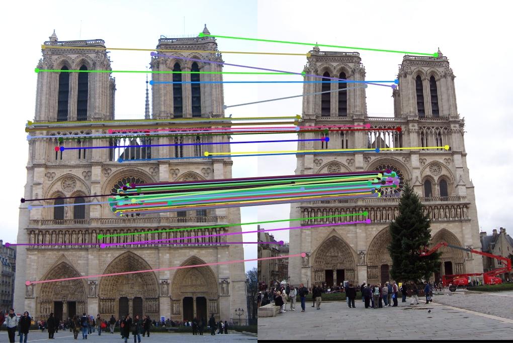
The following image shows an example of image matching in which same object in two different images, taken from different perspective, is matched based on keypoints.
Applications of Image Matching
Image matching has various real-world applications across different domains. In this section we discuss some of the key applications.
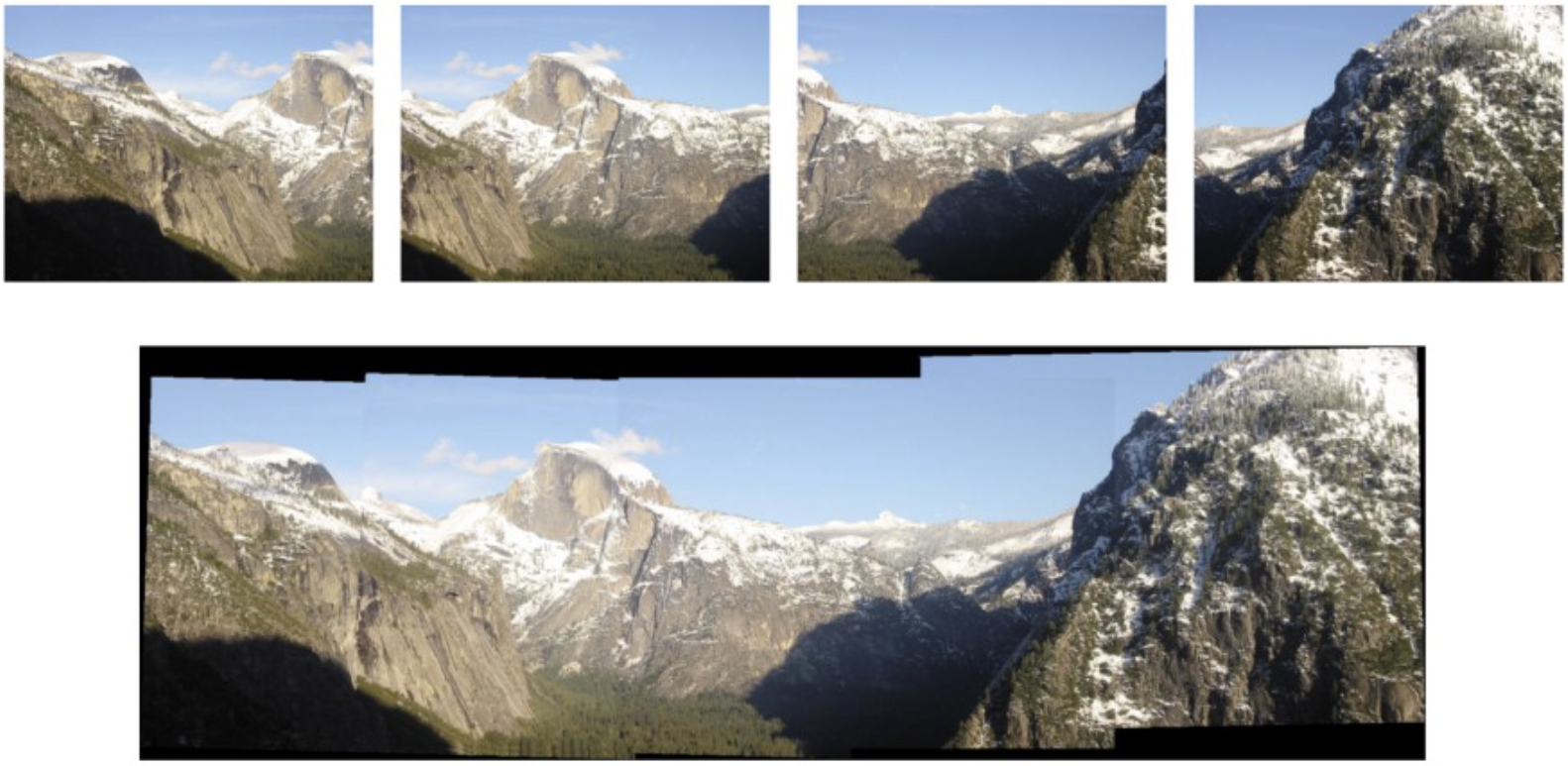
Image Stitching
Image stitching is the process of combining multiple images into a single panoramic image by aligning overlapping regions and blending them together seamlessly. Image stitching is commonly used in various applications such as:
- Creating panoramic photographs
- Creating wide-angle or 360-degree images for virtual tours
- Merging satellite images or aerial photographs
- Stitching together medical images for analysis or diagnosis
- Creating high-resolution images from multiple lower-resolution images
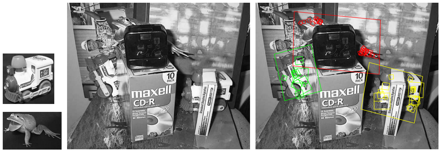
Object Recognition and Tracking
Object recognition and tracking refer to the processes of detecting and identifying objects in images or video streams, and then tracking their movement over time.
Object recognition and tracking are essential components of many computer vision applications, including:
- Surveillance: Tracking people or vehicles in video feeds for security purposes.
- Augmented Reality: Overlaying digital information or objects onto real-world scenes.
- Autonomous Vehicles: Tracking other vehicles, pedestrians, and obstacles for navigation and collision avoidance.
- Robotics: Identifying and tracking objects for robotic manipulation tasks.
- Human-Computer Interaction: Tracking hand gestures or facial expressions for user interaction.
- Medical Imaging: Tracking the movement of organs or tumors in medical images for diagnosis and treatment planning.
Image Registration
Image registration refers to the process of aligning two or more images so that corresponding features or points in the images are spatially aligned. The goal is to find a transformation that maps points from one image to corresponding points in another image.
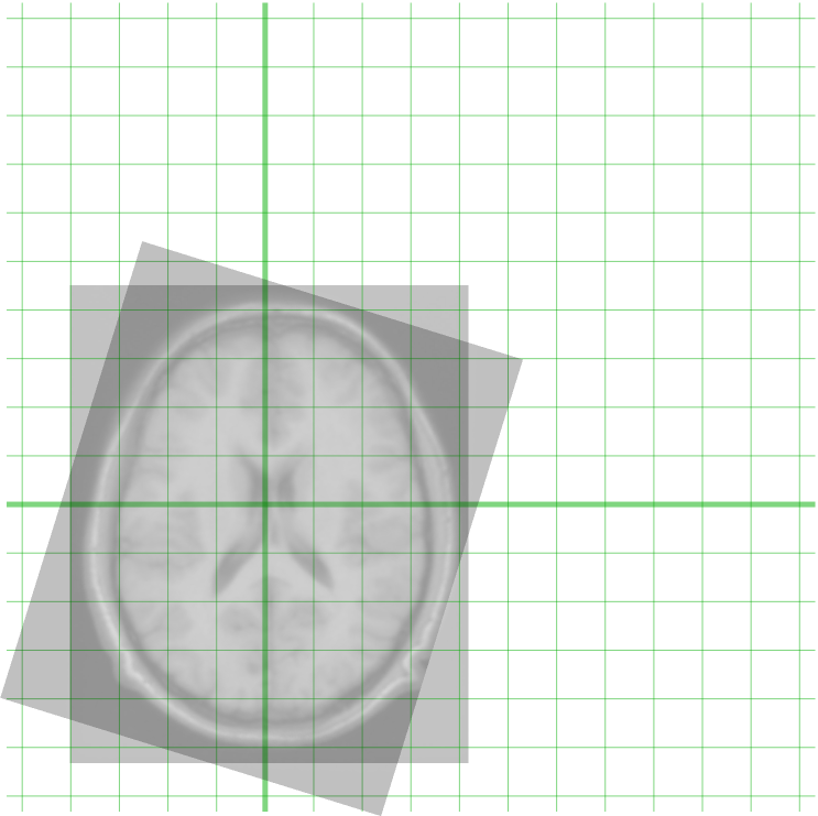
Image Registration of two MRI images of brain (Source)
Image Matching Techniques
There are several approaches to image matching. We will discuss two of the most common approaches here.
- Feature-based matching
- Template Matching
Feature-based matching
This method involves identifying distinctive features (such as corners, edges, or blobs) in the images and matching them based on their descriptors. Some common and popular algorithms used for feature-based matching include SIFT (Scale-Invariant Feature Transform), SURF (Speeded-Up Robust Features), ORB (Oriented FAST and Rotated BRIEF), AKAZE (Accelerated-KAZE), BRISK (Binary Robust Invariant Scalable Keypoints), and FREAK (Fast Retina Keypoint).
Feature based matching involves following two important steps.
- Detect keypoints and descriptors: Detect distinctive points or regions in both images that are likely to be matched and extract numerical descriptors or feature vectors around each keypoint to describe its local neighborhood. These descriptors should be distinctive and invariant to changes in scale, rotation, and illumination. Algorithms such as SIFT used for this process.
- Match keypoints: Compare the descriptors of keypoints between the two images to find correspondences. We may apply filtering techniques to remove incorrect matches and retain only reliable correspondences. Different feature matcher such as Brute-Force matcher, FLANN matcher are used for this process.
We’ll now see some examples of feature based matching.
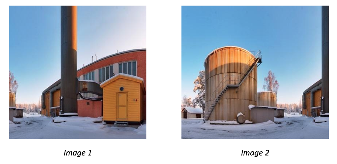
Example #1: Image Stitching
In this example we will combine the following two images to make it one wider image containing scene from both images.
After stitching both the images, the final output image will look like following.
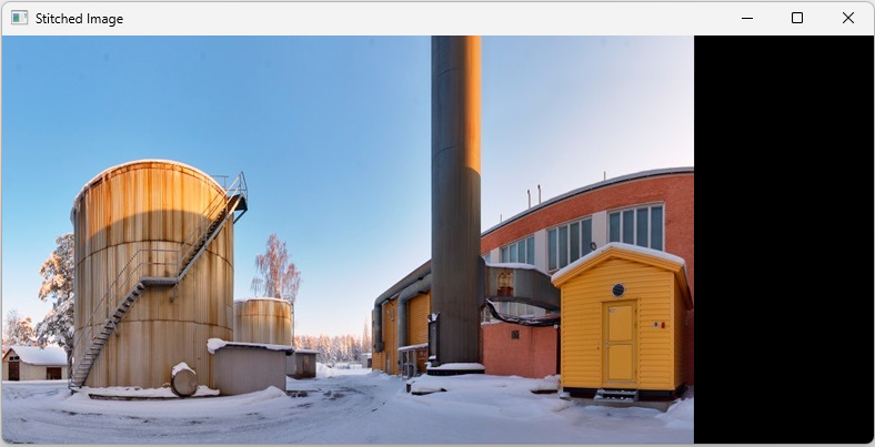
The following is the code for image stitching.
import cv2
import numpy as np

# Load images
image1 = cv2.imread('image1.jpg')
image2 = cv2.imread('image2.jpg')

# Convert images to grayscale
gray1 = cv2.cvtColor(image1, cv2.COLOR_BGR2GRAY)
gray2 = cv2.cvtColor(image2, cv2.COLOR_BGR2GRAY)

# Initialize SIFT detector
sift = cv2.SIFT_create()

# Detect keypoints and descriptors
keypoints1, descriptors1 = sift.detectAndCompute(gray1, None)
keypoints2, descriptors2 = sift.detectAndCompute(gray2, None)

# Initialize Brute Force matcher
bf = cv2.BFMatcher()

# Match descriptors
matches = bf.knnMatch(descriptors1, descriptors2, k=2)

# Ratio test to find good matches
good_matches = []
for m, n in matches:
    if m.distance < 0.7 * n.distance:
        good_matches.append(m)

# Extract keypoints of good matches
src_pts = np.float32([keypoints1[m.queryIdx].pt for m in good_matches]).reshape(-1, 1, 2)
dst_pts = np.float32([keypoints2[m.trainIdx].pt for m in good_matches]).reshape(-1, 1, 2)

# Find homography
H, _ = cv2.findHomography(src_pts, dst_pts, cv2.RANSAC, 5.0)

# Warp image1 to image2
stitched_image = cv2.warpPerspective(image1, H, (image2.shape[1] + image1.shape[1], image2.shape[0]))
stitched_image[:, :image2.shape[1]] = image2

# Display the stitched image
cv2.imshow('Stitched Image', stitched_image)
cv2.waitKey(0)
cv2.destroyAllWindows()
Example #2: Object Tracking
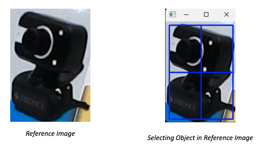
In this example, we detected keypoints and their descriptors of an object of our choice to track the object in subsequent video frames and calculate the transformation (translation, rotation, scale) between the keypoints in the reference image and the keypoints in the current video frame. Then, apply the transformation to the reference image to align it with the current frame and finally draw the tracked object on the frame. Following is the code. The code will first load the reference image and allow user to select the region of interest (ROI) in the reference image using mouse, it will then track the selected region of interest in the video frame.
Here’s the code to achieve above output.
import cv2
import numpy as np

# Load the reference image
reference_image = cv2.imread('reference_image.jpg')

# Convert reference image to grayscale
gray_reference = cv2.cvtColor(reference_image, cv2.COLOR_BGR2GRAY)

# Initialize SIFT detector
sift = cv2.SIFT_create()

# Detect keypoints and compute descriptors for the reference image
keypoints_reference, descriptors_reference = sift.detectAndCompute(gray_reference, None)

# Convert descriptors to CV_32F type
descriptors_reference = descriptors_reference.astype(np.float32)

# Initialize the camera or video stream
cap = cv2.VideoCapture(1)

# Select ROI on the reference image
bbox = cv2.selectROI('Select ROI', reference_image, fromCenter=False, showCrosshair=True)
x, y, w, h = bbox

# Extract keypoints and descriptors from the selected region
roi = gray_reference[y:y+h, x:x+w]
keypoints_roi, descriptors_roi = sift.detectAndCompute(roi, None)


# Convert descriptors to CV_32F type
descriptors_roi = descriptors_roi.astype(np.float32)

# Initialize the BFMatcher
bf = cv2.BFMatcher()

while True:
    # Capture frame-by-frame
    ret, frame = cap.read()
    gray_frame = cv2.cvtColor(frame, cv2.COLOR_BGR2GRAY)

    # Detect keypoints and compute descriptors for the frame
    keypoints_frame, descriptors_frame = sift.detectAndCompute(gray_frame, None)

    # Convert descriptors to CV_32F type
    descriptors_frame = descriptors_frame.astype(np.float32)

    # Match descriptors between the frame and the reference region
    matches = bf.knnMatch(descriptors_roi, descriptors_frame, k=2)

    # Apply ratio test to find good matches
    good_matches = []
    for m, n in matches:
        if m.distance < 0.75 * n.distance:
            good_matches.append(m)

    # Calculate homography
    if len(good_matches) > 10:
        src_pts = np.float32([keypoints_roi[m.queryIdx].pt for m in good_matches]).reshape(-1, 1, 2)
        dst_pts = np.float32([keypoints_frame[m.trainIdx].pt for m in good_matches]).reshape(-1, 1, 2)
        M, _ = cv2.findHomography(src_pts, dst_pts, cv2.RANSAC, 5.0)
        if M is not None:
            # Calculate bounding box for the tracked object
            pts = np.float32([[0, 0], [0, h - 1], [w - 1, h - 1], [w - 1, 0]]).reshape(-1, 1, 2)
            dst = cv2.perspectiveTransform(pts, M)
            frame = cv2.polylines(frame, [np.int32(dst)], True, (0, 255, 0), 2)


    # Display the frame with the tracked object
    cv2.imshow('Object Tracking', frame)

    # Exit if 'q' is pressed
    if cv2.waitKey(1) & 0xFF == ord('q'):
        break

# Release the capture
cap.release()
cv2.destroyAllWindows()
Example #2: Augmented Reality Example
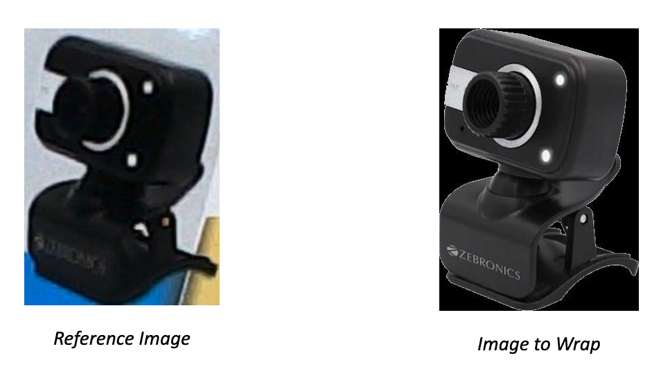
In this example we detect keypoints and match them between the reference image and the frames from the camera. Then, calculate the homography matrix using the matched keypoints and warp the virtual object (another image) or information using the homography matrix to align it with the reference image in the camera frame. Finally, overlay the virtual object or information onto the camera frame.
In the code we overlay the following reference image with the PNG image of camera below.
import cv2
import numpy as np

# Load the reference image
reference_image = cv2.imread('reference_image.jpg')

# Load the image to wrap onto the reference image
image_to_wrap = cv2.imread('cam.png')

# Resize the image to match the size of the reference image
image_to_wrap_resized = cv2.resize(image_to_wrap, (reference_image.shape[1], reference_image.shape[0]))

# Convert reference image to grayscale
gray_reference = cv2.cvtColor(reference_image, cv2.COLOR_BGR2GRAY)

# Initialize SIFT detector
sift = cv2.SIFT_create()

# Detect keypoints and compute descriptors for the reference image
keypoints_reference, descriptors_reference = sift.detectAndCompute(gray_reference, None)

# Initialize the camera or video stream
cap = cv2.VideoCapture(1)

while True:
    # Capture frame-by-frame
    ret, frame = cap.read()

    # Convert frame to grayscale
    gray_frame = cv2.cvtColor(frame, cv2.COLOR_BGR2GRAY)

    # Detect keypoints and compute descriptors for the frame
    keypoints_frame, descriptors_frame = sift.detectAndCompute(gray_frame, None)

    if descriptors_frame is not None:
        # Match descriptors between the frame and the reference image
        bf = cv2.BFMatcher()
        matches = bf.knnMatch(descriptors_reference, descriptors_frame, k=2)

        # Apply ratio test to find good matches
        good_matches = []
        for m, n in matches:
            if m.distance < 0.75 * n.distance:
                good_matches.append(m)

        if len(good_matches) > 10:
            # Get the matched keypoints
            src_pts = np.float32([keypoints_reference[m.queryIdx].pt for m in good_matches]).reshape(-1, 1, 2)
            dst_pts = np.float32([keypoints_frame[m.trainIdx].pt for m in good_matches]).reshape(-1, 1, 2)

            # Calculate homography
            M, _ = cv2.findHomography(src_pts, dst_pts, cv2.RANSAC, 5.0)
            if M is not None:
                # Warp the image to fit the perspective of the reference image
                warped_image = cv2.warpPerspective(image_to_wrap_resized, M, (frame.shape[1], frame.shape[0]))

                # Overlay the warped image onto the frame
                frame_with_overlay = frame.copy()
                frame_with_overlay[np.where(warped_image[:, :, 0] != 0)] = warped_image[np.where(warped_image[:, :, 0] != 0)]

                # Display the frame with overlay
                cv2.imshow('Augmented Reality', frame_with_overlay)
            else:
                cv2.imshow('Augmented Reality', frame)

        else:
            cv2.imshow('Augmented Reality', frame)

    else:
        cv2.imshow('Augmented Reality', frame)

    # Exit if 'q' is pressed
    if cv2.waitKey(1) & 0xFF == ord('q'):
        break

# Release the capture
cap.release()
cv2.destroyAllWindows()
Template matching
Template matching is a technique used in image processing and computer vision to find a template image within a larger image. It involves sliding the template image over the larger image and comparing their pixel values or features to find the best match. Here's how it works in detail:
- Input Images: You have a template image and a larger image within which you want to find occurrences of the template.
- Sliding Window: The template image is moved (or "slid") over the larger image in a systematic way, usually pixel by pixel or in larger strides.
- Comparison: At each position of the template, a similarity measure is computed between the template and the corresponding region in the larger image. This measure can be based on pixel-wise differences, correlation coefficients, or other metrics depending on the application.
- Best Match: The position with the highest similarity measure indicates the best match of the template within the larger image.
OpenCV provides matchTemplate() function for template matching. There are the different comparison methods used in template matching. Each method has its own way of computing the similarity between the template and the target image. These are following:
- TM_CCOEFF: This method computes the correlation coefficient between the template and the target images.
- TM_CCOEFF_NORMED: This method computes the normalized correlation coefficient.
- TM_CCORR: It calculates the cross-correlation between the template and the image.
- TM_CCORR_NORMED: Similar to TM_CCORR but normalized.
- TM_SQDIFF: This method computes the sum of squared differences between the template and the target images.
- TM_SQDIFF_NORMED: This method computes the normalized sum of squared differences between the template and the target images.
One practical example of using template matching in image processing is in automated quality control in manufacturing. Let's consider a scenario where you have a production line manufacturing circuit boards. Each board should have a specific configuration of components placed accurately on it. However, due to various reasons such as machine error or component defects, sometimes these components might be misplaced or missing. Template matching can be used to detect these defects. Here's how it works:
- Template Creation: First, you create a template image that represents the correct configuration of components on the circuit board. This template could be a high-resolution image of an ideal circuit board.
- Image Acquisition: As each circuit board moves along the production line, a camera takes an image of it.
- Template Matching: The acquired image is then compared with the template using template matching algorithms.
- Defect Detection: If the similarity score falls below a certain threshold, it indicates that the components on the circuit board are not in the correct position or are missing. This alerts the system to a potential defect, and appropriate action can be taken, such as marking the defective board for manual inspection or rejection.
We’ll now see this through an example. I am using following images as a template to be tested in the main circuit board image.
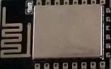
Template Images
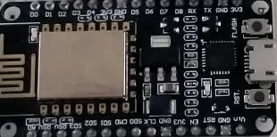
And following is my main circuit image to be examined for whether it has all of these components.
Following is the output of the program.
Here’s the code for the template matching example:
import cv2
import numpy as np
import tkinter as tk
from tkinter import filedialog

def template_match(template, target, method=cv2.TM_CCOEFF_NORMED, threshold=0.8):
    """
    Perform template matching
    """
    template_gray = cv2.cvtColor(template, cv2.COLOR_BGR2GRAY)
    target_gray = cv2.cvtColor(target, cv2.COLOR_BGR2GRAY)

    result = cv2.matchTemplate(target_gray, template_gray, method)
    min_val, max_val, min_loc, max_loc = cv2.minMaxLoc(result)

    if max_val >= threshold:
        template_height, template_width = template_gray.shape[:2]

        if method in [cv2.TM_SQDIFF, cv2.TM_SQDIFF_NORMED]:
            top_left = min_loc
        else:
            top_left = max_loc

        bottom_right = (top_left[0] + template_width, top_left[1] + template_height)
        return [(top_left, bottom_right, 0)]
    else:
        return []

def upload_image(label):
    filename = filedialog.askopenfilename()
    if filename:
        img = cv2.imread(filename)
        label.config(text=f"Image: {filename}")
        return img

def display_matched_result():
    template_img = template_image_label.cget("text").split(": ")[1]
    target_img = target_image_label.cget("text").split(": ")[1]
    method = method_var.get()
    threshold = float(threshold_entry.get())

    if template_img and target_img:
        template = cv2.imread(template_img)
        target = cv2.imread(target_img)

        method_dict = {
            "TM_CCOEFF": cv2.TM_CCOEFF,
            "TM_CCOEFF_NORMED": cv2.TM_CCOEFF_NORMED,
            "TM_CCORR": cv2.TM_CCORR,
            "TM_CCORR_NORMED": cv2.TM_CCORR_NORMED,
            "TM_SQDIFF": cv2.TM_SQDIFF,
            "TM_SQDIFF_NORMED": cv2.TM_SQDIFF_NORMED
        }
        selected_method = method_dict[method]

        matches = template_match(template, target, selected_method, threshold)

        for match in matches:
            top_left, bottom_right, _ = match
            cv2.rectangle(target, top_left, bottom_right, (0, 255, 0), 2)

        cv2.imshow('Matched Regions', target)
        cv2.waitKey(0)
        cv2.destroyAllWindows()

# GUI
root = tk.Tk()
root.title("Template Matching")

# Template Image
template_image_label = tk.Label(root, text="Template Image:")
template_image_label.grid(row=0, column=0, padx=10, pady=10)
template_image_button = tk.Button(root, text="Upload Template Image", command=lambda: upload_image(template_image_label))
template_image_button.grid(row=0, column=1, padx=10, pady=10)

# Target Image
target_image_label = tk.Label(root, text="Target Image:")
target_image_label.grid(row=1, column=0, padx=10, pady=10)
target_image_button = tk.Button(root, text="Upload Target Image", command=lambda: upload_image(target_image_label))
target_image_button.grid(row=1, column=1, padx=10, pady=10)

# Method Selection
method_label = tk.Label(root, text="Select Method:")
method_label.grid(row=2, column=0, padx=10, pady=10)
method_options = ["TM_CCOEFF", "TM_CCOEFF_NORMED", "TM_CCORR", "TM_CCORR_NORMED", "TM_SQDIFF", "TM_SQDIFF_NORMED"]
method_var = tk.StringVar(root)
method_var.set(method_options[1])  # Default method
method_dropdown = tk.OptionMenu(root, method_var, *method_options)
method_dropdown.grid(row=2, column=1, padx=10, pady=10)

# Threshold
threshold_label = tk.Label(root, text="Threshold:")
threshold_label.grid(row=3, column=0, padx=10, pady=10)
threshold_entry = tk.Entry(root)
threshold_entry.insert(tk.END, "0.8")  # Default threshold
threshold_entry.grid(row=3, column=1, padx=10, pady=10)

# Match Button
match_button = tk.Button(root, text="Match", command=display_matched_result)
match_button.grid(row=4, column=0, columnspan=2, padx=10, pady=10)

root.mainloop()
Conclusion
Image matching is a powerful technique in computer vision that enables various applications such as object recognition, image registration, and image reconstruction.
In this blog post, we learned about feature-based matching and template matching through examples.
Feature-based matching involves identifying and matching key features or keypoints between two images. These keypoints are distinctive points in the image, such as corners, edges, or blobs, that are invariant to changes in scale, rotation, and illumination.
Template matching, on the other hand, involves comparing a template image (or pattern) with a larger search image to locate instances of the template within the search image. The template is moved across the search image, and a similarity metric is computed at each position to determine the degree of match.
Both feature-based matching and template matching have their strengths and weaknesses, and the choice between them depends on factors such as the nature of the problem, computational requirements, and the desired level of robustness. Understanding the principles and characteristics of these techniques is essential for effectively solving various computer vision tasks.
Cite this Post
Use the following entry to cite this post in your research:
Timothy M. (May 20, 2024). What is Image Matching? An Introduction.. Roboflow Blog: https://blog.roboflow.com/image-matching/