
Part inspection is a quality control process used in manufacturing to ensure that individual components or assembled products meet specified standards and tolerances. This process involves verifying the presence, size, shape, alignment, color, integrity, and correct assembly of parts before they proceed to the next stage of production or shipment.
Traditionally, part inspection was performed manually by human inspectors, which can be time-consuming, subjective, and prone to error. Today, manufacturers increasingly rely on computer vision (CV) that enables machines to “see” and interpret visual information, to automate and enhance the inspection process.
Part inspection using computer vision refers to automated visual inspection processes in manufacturing that uses cameras, sensors, and AI models to analyze, identify, measure, or verify the quality and conformity of manufactured components. It replaces or augments manual inspection, significantly enhancing speed, consistency, accuracy, and reliability.
Applications of Computer Vision in Part Inspection
We will now explore different application used in computer vision assisted part inspection.
Missing Parts Inspection
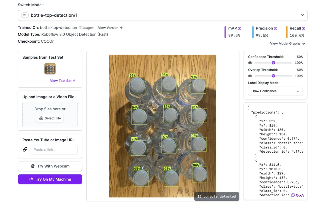
Missing part inspection using computer vision refers to the automated process of verifying whether all required components of a product or assembly are present. Additionally, missing part inspection also involve checking whether all the expected items are present in a package. For example, if a box is supposed to contain six bottles, the system makes sure none are missing. Using image data and trained CV models, the system checks for the absence of expected parts, such as screws, caps, labels, or count of packaged items, on a product or in a container. If a component is absent, the system flags the discrepancy instantly, preventing incomplete products from moving further down the production line.
To build missing parts inspection application, an object detection model can be trained to identify missing items in product packaging. For example, consider verifying that a box contains the correct number of bottles before sealing and distribution. Using computer vision, we can detect and count bottle tops from a top-down view, ensuring that each package meets the required quantity.
Too Few, Too Many Parts, or Foreign Objects Inspection
"Too Few, Too Many Parts, or Foreign Objects" inspection in computer vision refers to detecting quantity mismatches or unwanted items in a product assembly or packaging. The goal is to ensure that only the correct number of expected components are present and nothing extra or unrelated has been included.
The computer vision system can automatically count and confirm that the correct number of parts are present. It quickly identifies any irregularities, such as extra components or misplaced foreign objects, and triggers alerts so that corrective action can be taken right away.
Imagine that in a pharmaceutical industry, a medical kit packaging should contain exactly 5 items, such as a syringe, alcohol swab, bandage, gloves, and instruction leaflet. A computer vision system scans each part of this assembled kit and alerts is:
- One item is missing (too few), it flags the kit.
- An extra swab is packed (too many), it detects redundancy.
- An unrelated item (e.g., a pen or piece of plastic) is inside, it identifies it as a foreign object.
Incorrect Assembly of Parts Inspection
Computer vision systems can be used to verify the correct positioning and orientation of components while assembling a product. This system prompts immediately if there is any deviation from specified assembly parameters and ensuring parts are assembled accurately and consistently.
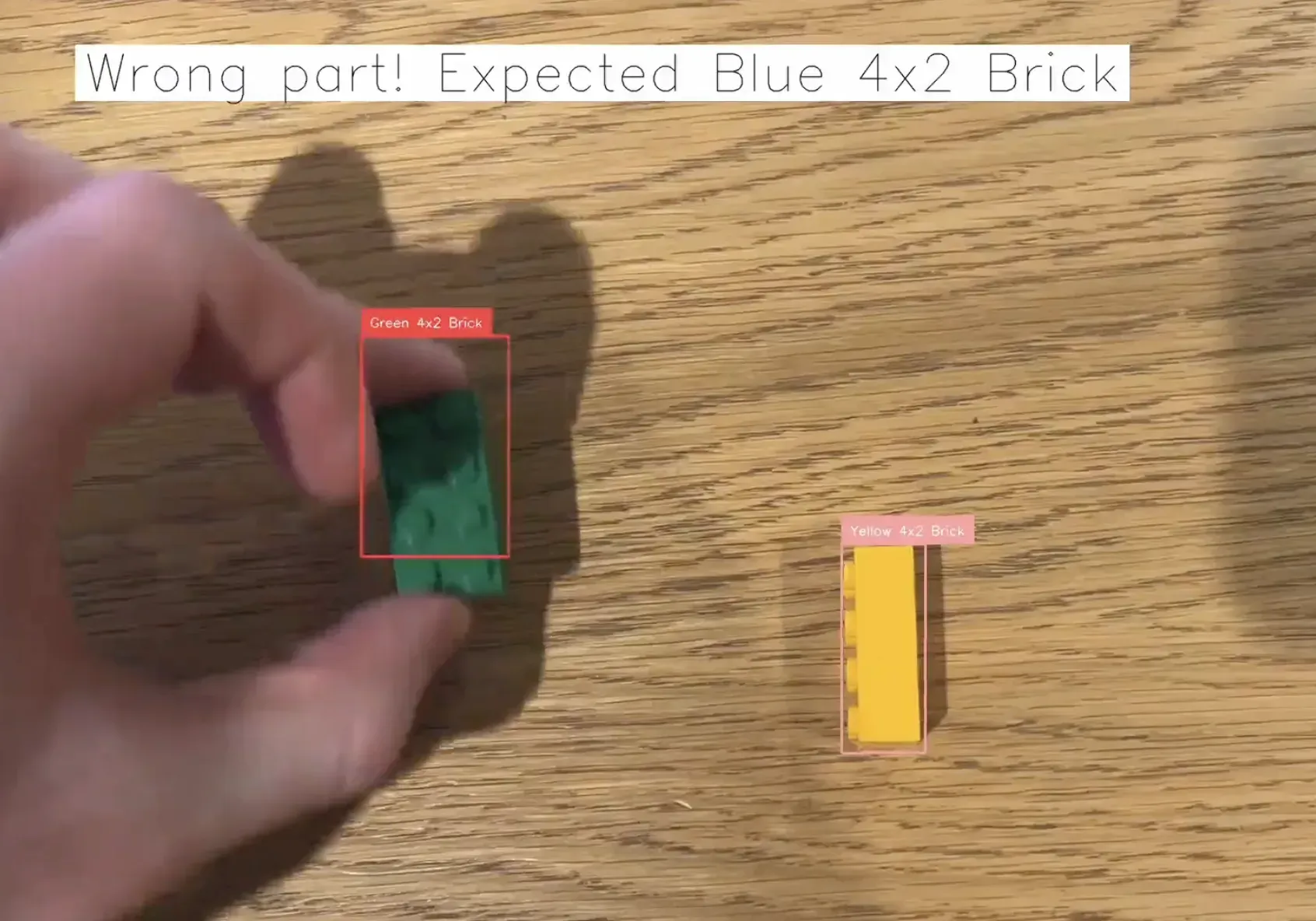
For example, consider building a manual assembly quality assurance (QA) system using computer vision, as outlined in the Roboflow blog post on How to Build a Manual Assembly QA System. The example illustrates a scenario where computer vision is employed to verify the correct assembly of products during manual manufacturing processes. Using LEGO bricks as an example, the system is designed to detect whether the assembler picks and places the correct parts in the specified order. This approach helps prevent errors such as using incorrect components or assembling parts in the wrong sequence, which could lead to product failures.
Defective Parts (Broken, Chipped, Dented, Cracked) Inspection
Computer vision systems are highly effective at identifying physical defects like breaks, chips, dents, or cracks. By employing high-resolution cameras with computer vision models, even subtle defects invisible to the naked eye can be quickly identified, categorized, and addressed.
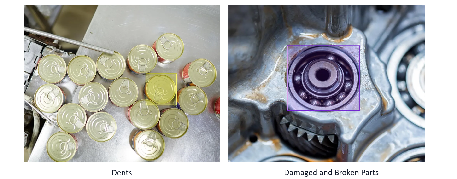
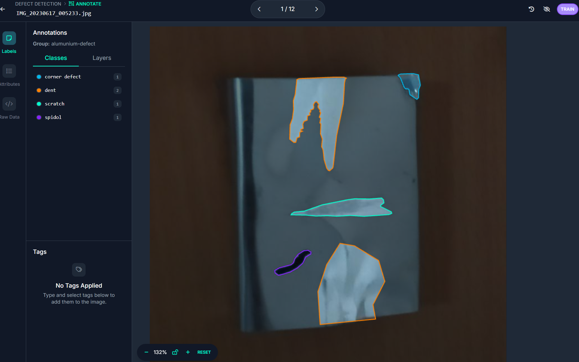
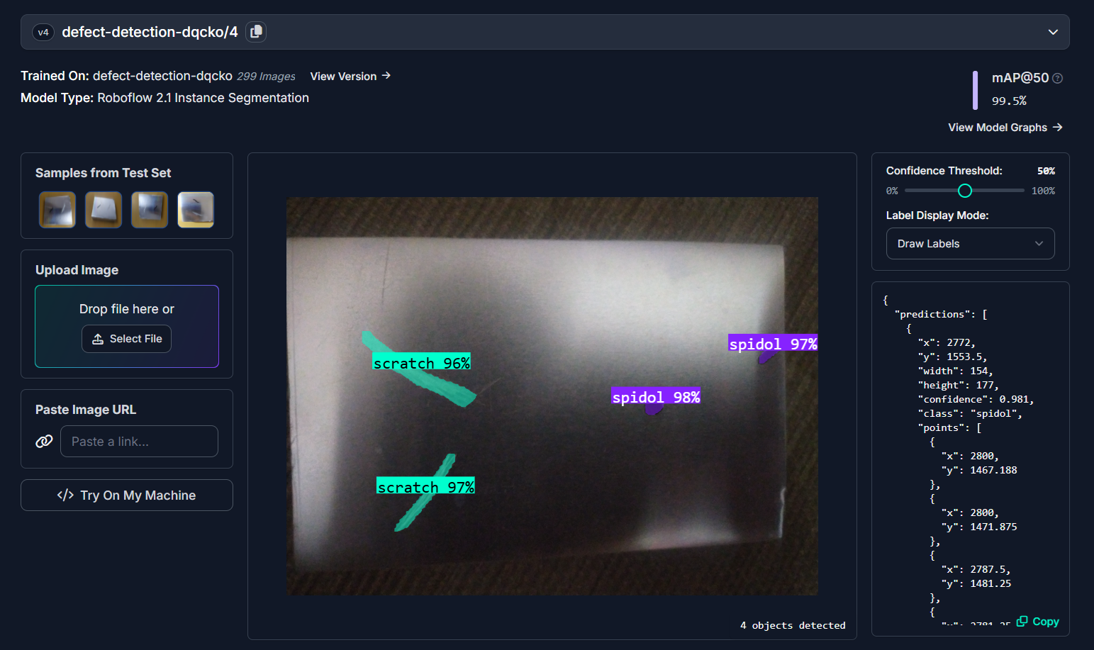
Object detection or instance segmentation models trained on custom dataset for defect detection can be used to identify defective parts such as broken, chipped, dented, or cracked surfaces. A good example is inspecting metal components for surface defects using computer vision. These defects, such as scratches, dents, or cracks, can compromise structural integrity or product appearance, making inspection a vital step in quality assurance. To build such a system, you can collect and label images of metal parts with and without defects, and train a computer vision model using a platform like Roboflow.
Once trained, the model can detect defects in real time on the production line, allowing manufacturers to flag and remove faulty parts immediately and maintain consistent quality standards throughout production.
Incorrect Color Inspection
Product color inspection refers to the use of computer vision to verify whether a product or component has the correct color as specified in design or quality standards. Color inspection can also be used to sort and pack products based on color types. For example, in a toy manufacturing line, red blocks and green blocks are packed into different boxes. A computer vision model checks the color of each block. If a red block is accidentally placed in the green set, it’s flagged and removed automatically, ensuring color-based sorting is accurate.
For example, a cloth manufacturing brand wants to automatically check the color of t-shirts coming off the production line to ensure they match the correct shade, like navy blue, maroon, or olive green. An instance segmentation model can be used to first segments the t-shirt from the background. This ensures that only the t-shirt area is analyzed, not the background or other parts. Then, the k-means clustering can be applied to the segmented pixels to identify the dominant color of the fabric. If the detected color doesn’t fall within the acceptable range for predefined color, the system flags it for review. This helps the brand maintain color consistency across products and avoid customer complaints or returns due to incorrect shades.
Parts Not Sealed or Closed
Computer vision technologies, often combined with infrared or thermal imaging, effectively assess whether components or packages are properly sealed. These systems quickly highlight poorly sealed or partially open items, ensuring compliance with safety, durability, and quality standards.
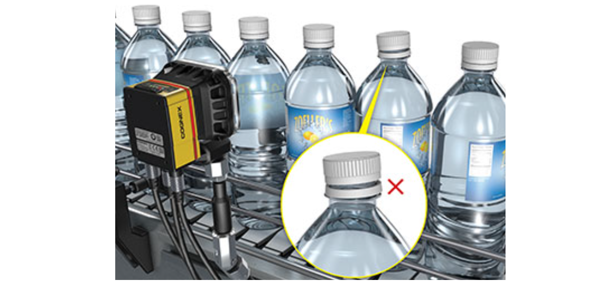
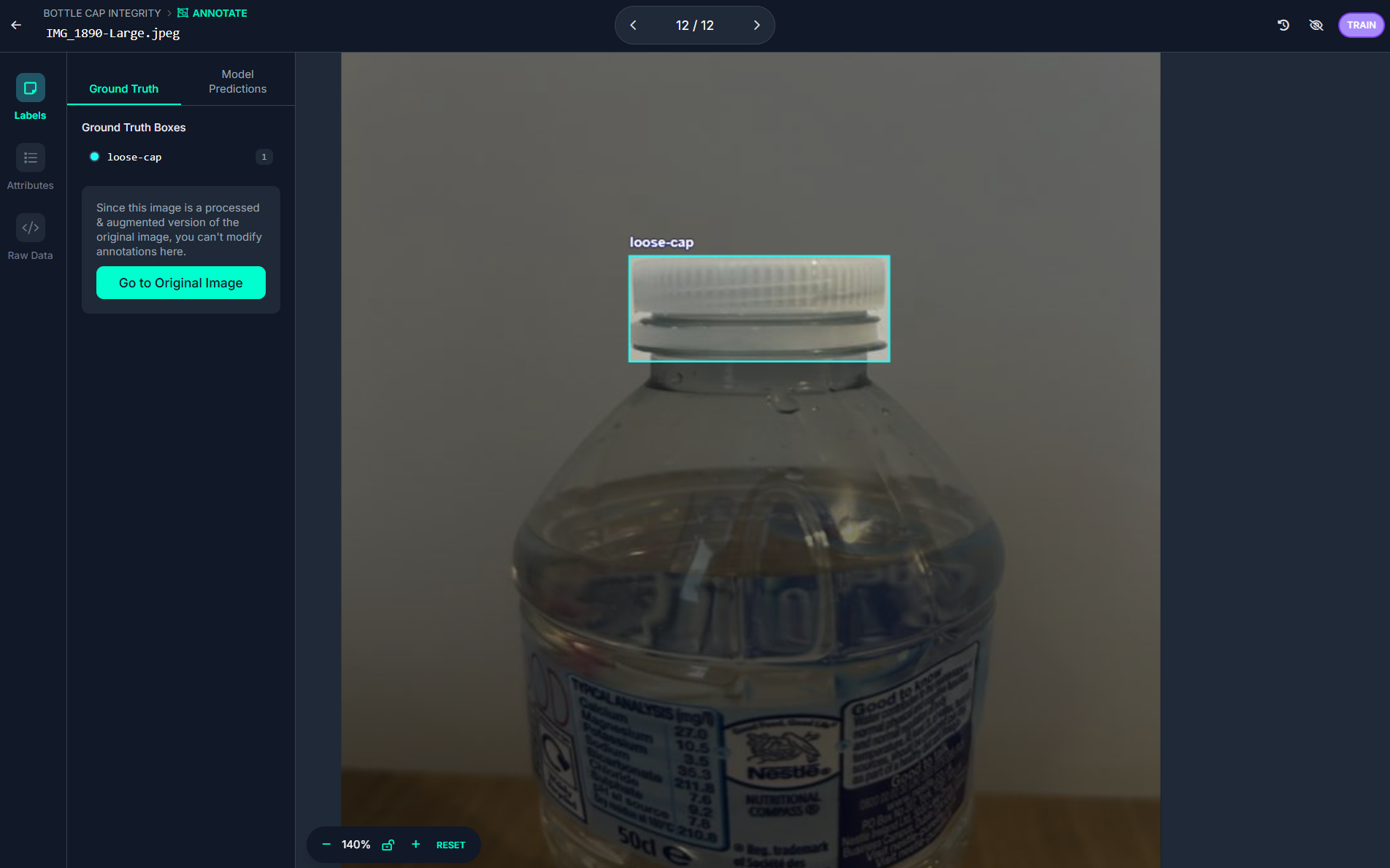
An object detection can be trained on custom dataset to detect whether parts of a product are properly sealed or not. Take the example of detecting whether a bottle cap is sealed using computer vision to inspect bottle caps on an assembly line.
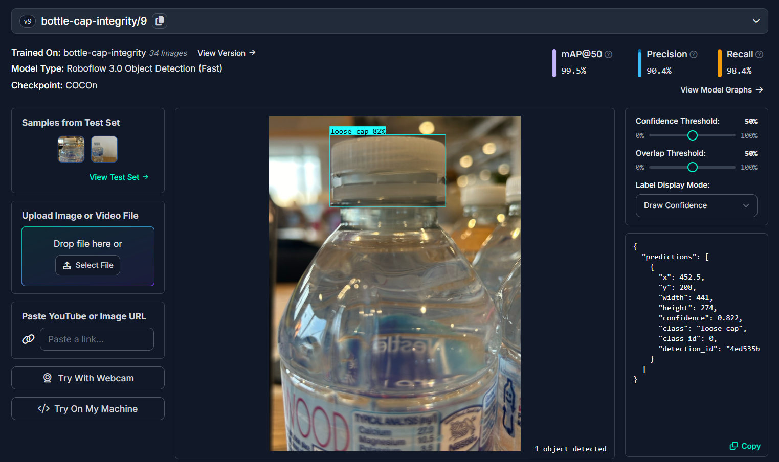
The goal is to automatically identify whether a bottle cap is properly sealed, loose or not properly sealed, or missing entirely. This type of inspection is crucial to ensure product quality before packaging and distribution. You can train this model by collecting an image dataset of sealed and unsealed bottle caps. The images then can be labeled as loose-cap and sealed-cap classes and a computer vision model can be trained using Roboflow.
The resulting system can automatically detect and classify bottle caps in real-time, enabling immediate rejection of defective products and tracking defect statistics over time for improved quality control.
Part Inspection Example
Let's now look at how to build a part inspection system using computer vision with Roboflow. In this example, we’ll focus on detecting cases where there are too few components, too many, or foreign objects on a product. Take a use case from the PCB manufacturing industry, during the inspection stage, a computer vision system checks whether essential components like resistors, diodes, capacitors, and ICs are all present in the required number on the circuit board.
Let’s say a specific PCB design requires:
- 10 resistors
- 4 diodes
- 6 capacitors
- 2 integrated circuits (ICs)
A camera captures high-resolution images of each assembled PCB, and a trained object detection model identifies and counts each type of component.
- If only 9 resistors are detected, it's flagged as too few.
- If an extra capacitor is found, it's too many.
- If a wrong component (like a diode in place of a capacitor) is detected, it's a foreign object or incorrect part.
This ensures each board meets design specifications and avoids functional failures due to missing or misplaced components. It is especially useful in high-speed SMT (Surface Mount Technology) lines where manual inspection is too slow or error-prone.
Step #1: Build The PCB component detection model
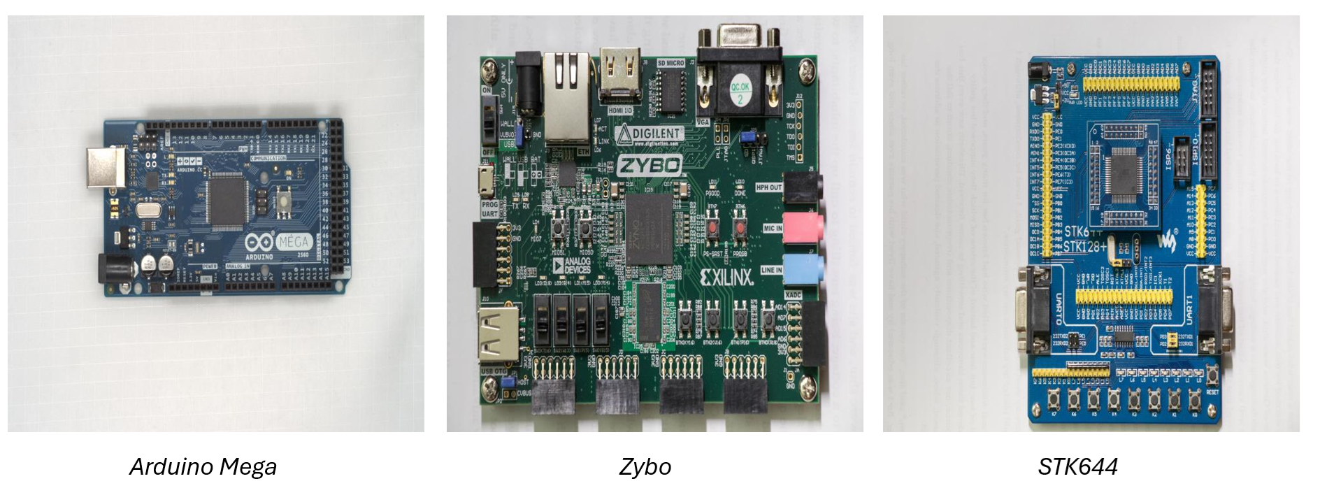
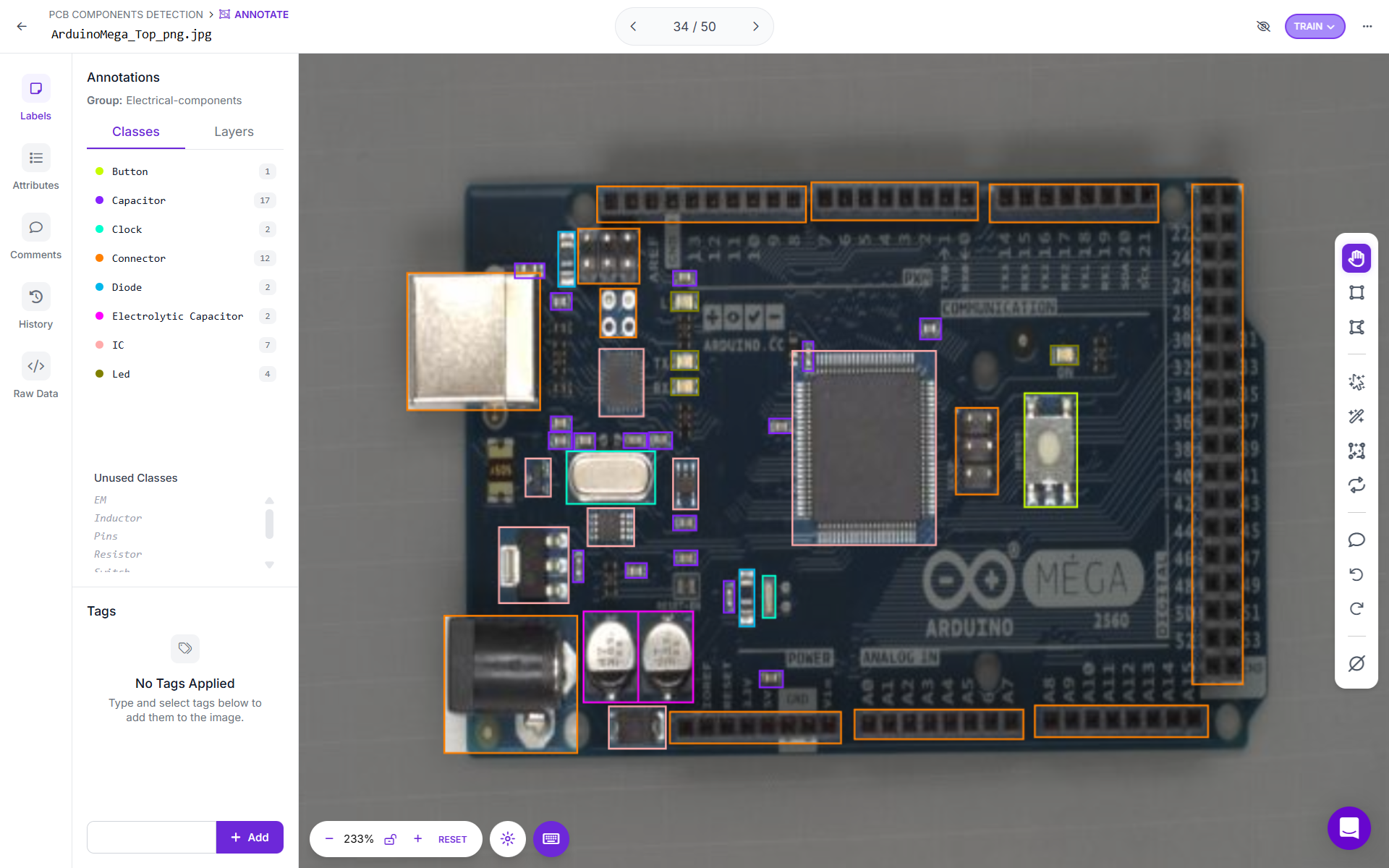
To build this example, images of various hardware kits and circuit boards were collected to build a diverse dataset.
The collected images were uploaded to Roboflow and annotated with class labels for different components such as Button, Capacitor, Clock, Connector, Diode, Electrolytic Capacitor, IC, Inductor, LED, Pins, Resistor, Switch, and Transistor. Each image was carefully labeled to enable the model to accurately identify and distinguish between these components.
After completing the annotation process, the dataset was prepared and the model was trained using Roboflow Auto-Train.
The PCB Component Detection Model ensure that PCBs contain all essential components, such as the correct number and type of ICs, capacitors, resistors, and other critical hardware elements, before moving to the next stage of production. For example, if a PCB requires 2 ICs, 4 resistors, and 5 diodes, and the model successfully detects all components as specified, it may return a message like “PCB OK.” However, if the model detects 2 ICs, 4 resistors, 4 diodes, and 1 capacitor, it could trigger an alert stating: “1 diode missing; 1 foreign object detected – capacitor found.”
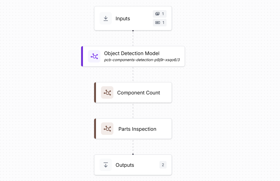
Step #2: Building the Roboflow Workflow
Now we will build the Roboflow Workflow to detect and count various components on a PCB. The workflow will analyze an input image, identify each component, and display the count for every detected class. The Workflow looks like following.
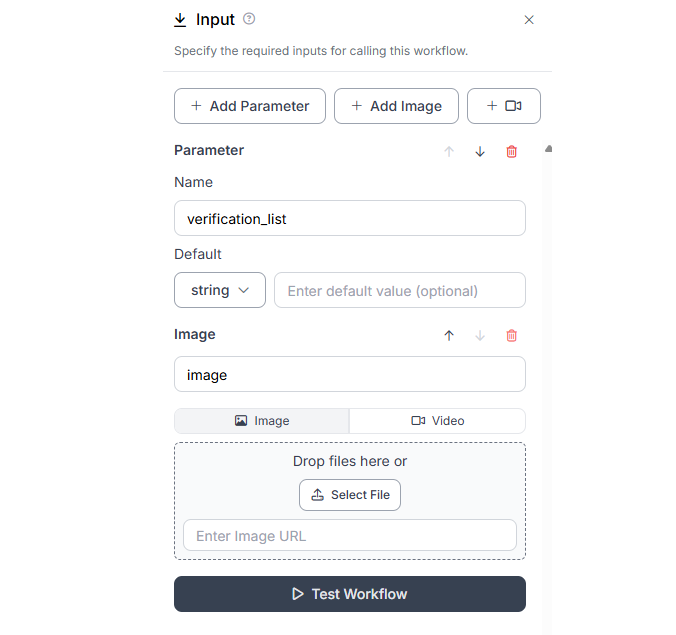
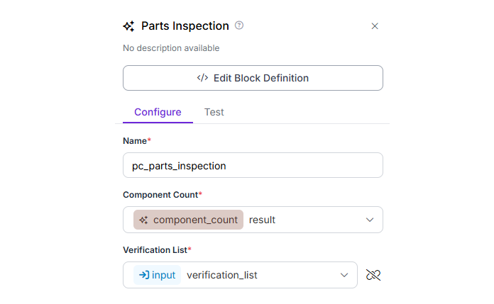
To build this workflow, firse configure the input block by adding input parameter verification_list along with image as follows. The verification_list parameter is used to provide a list of required components and their expected counts to the Part Inspection custom Python block. This allows the block to compare the detected components with the expected values and verify if everything is correctly placed on the PCB.
and then add Object Detection Model block and configure it with the previously trained PCB component detection model.
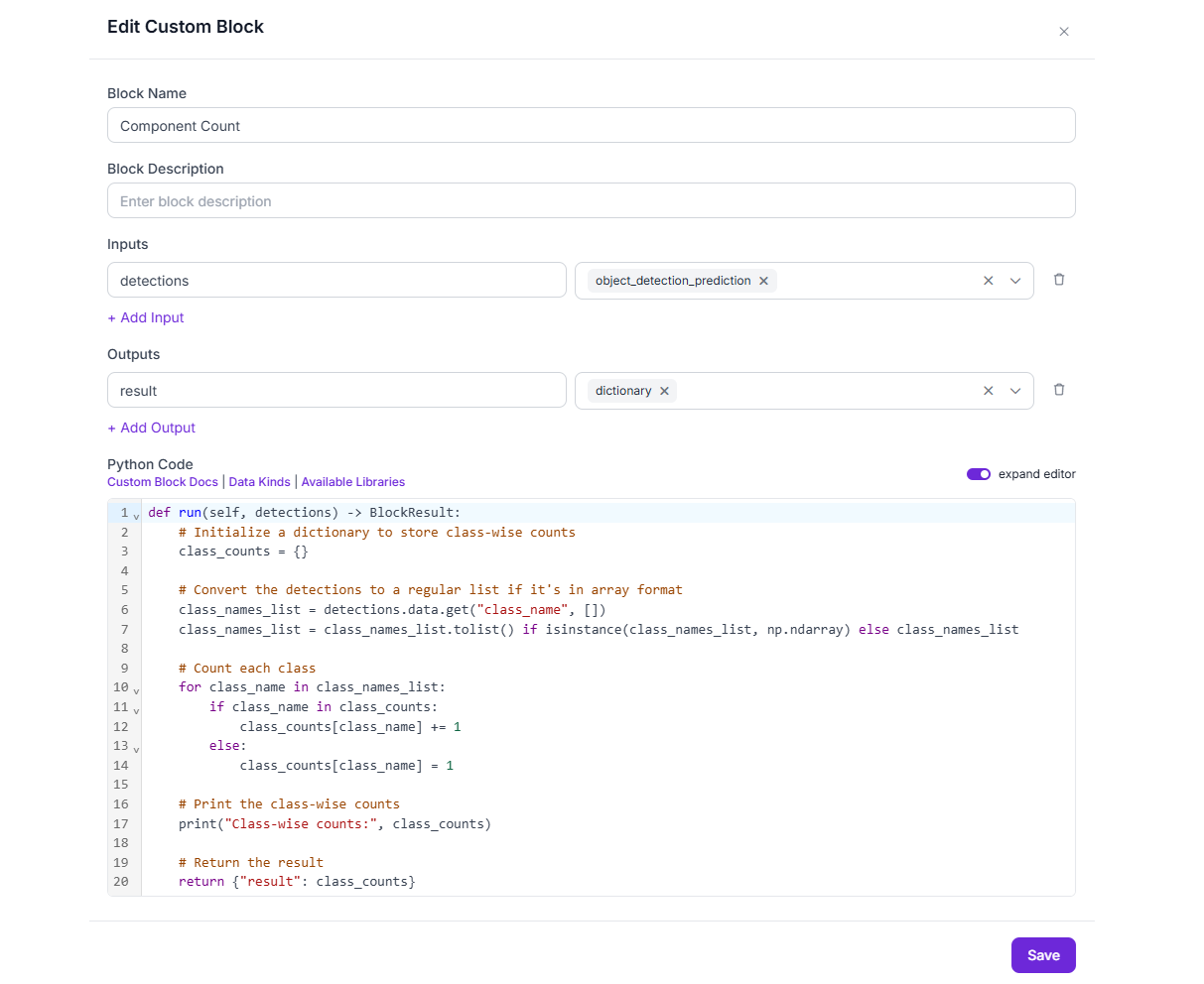
In this workflow, we will add two Custom Python blocks i.e. Component Count block and Parts Inspection block. The first Component Count python block will calculate the count of each component type detected by the model, helping to verify whether the PCB contains the correct number of required components and ensuring inspection accuracy. Add a Custom Python Block to the workflow and insert the following code to process the detection results to count PCB components.
def run(self, detections) -> BlockResult:
    # Initialize a dictionary to store class-wise counts
    class_counts = {}

    # Convert the detections to a regular list if it's in array format
    class_names_list = detections.data.get("class_name", [])
    class_names_list = class_names_list.tolist() if isinstance(class_names_list, np.ndarray) else class_names_list

    # Count each class
    for class_name in class_names_list:
        if class_name in class_counts:
            class_counts[class_name] += 1
        else:
            class_counts[class_name] = 1

    # Print the class-wise counts
    print("Class-wise counts:", class_counts)

    # Return the result
    return {"result": class_counts}
The custom python block should look like following.
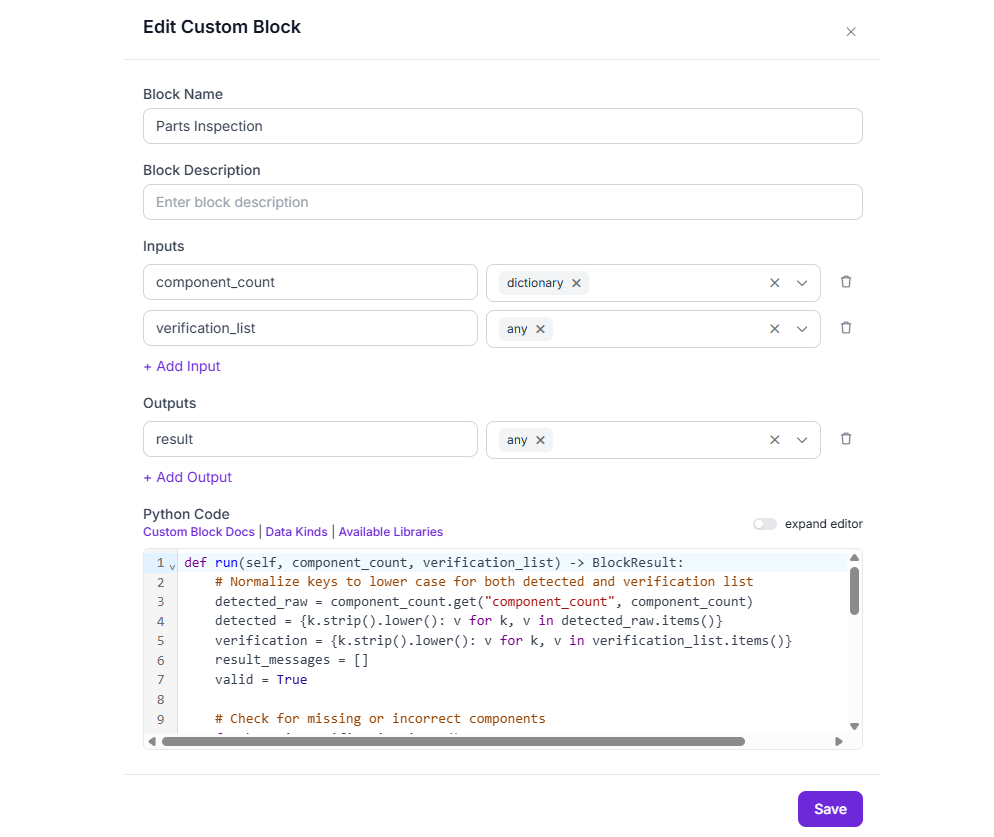
Now, add second Parts Inspection Custom Python block. This block will take input from first Python block and a verification list from input block. The code in this python block verifies whether the detected PCB components match an expected list. It normalizes the component names to lowercase, compares the detected and expected counts, identifies missing or extra components, and generates an appropriate message. If all components match correctly, it returns "PCB OK"; otherwise, it returns an alert with detailed discrepancies. Add the second Custom Python block and insert following code in it.
def run(self, component_count, verification_list) -> BlockResult:
    # Normalize keys to lower case for both detected and verification list
    detected_raw = component_count.get("component_count", component_count)
    detected = {k.strip().lower(): v for k, v in detected_raw.items()}
    verification = {k.strip().lower(): v for k, v in verification_list.items()}
    result_messages = []
    valid = True
    total_foreign_components = 0  # Counter for all foreign elements

    # Check for missing or incorrect components
    for k, v in verification.items():
        if k not in detected:
            result_messages.append(f"Missing component: {k}")
            valid = False
        elif detected[k] != v:
            result_messages.append(f"Count mismatch for {k}: detected {detected[k]}, expected {v}")
            valid = False

    # Check for extra/foreign elements, count each, and total
    for k in detected:
        if k not in verification:
            result_messages.append(f"Foreign component detected: {k} (count: {detected[k]})")
            total_foreign_components += detected[k]
            valid = False

    # Add total number of foreign components to message (if present)
    if total_foreign_components > 0:
        result_messages.append(f"Total number of foreign components: {total_foreign_components}")

    if valid:
        alert = "PCB OK"
    else:
        alert = "PCB Alert: " + "; ".join(result_messages)

    return {"result": alert}
The Parts Inspection block should look like following.
Then configure this python block as follows.
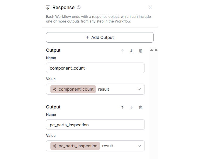
Finally, the output block should look like following.
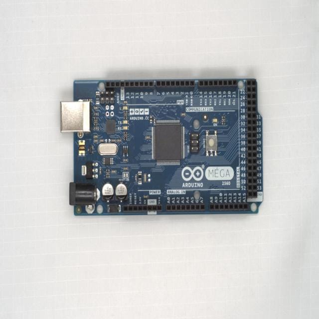
When you run the code for image below
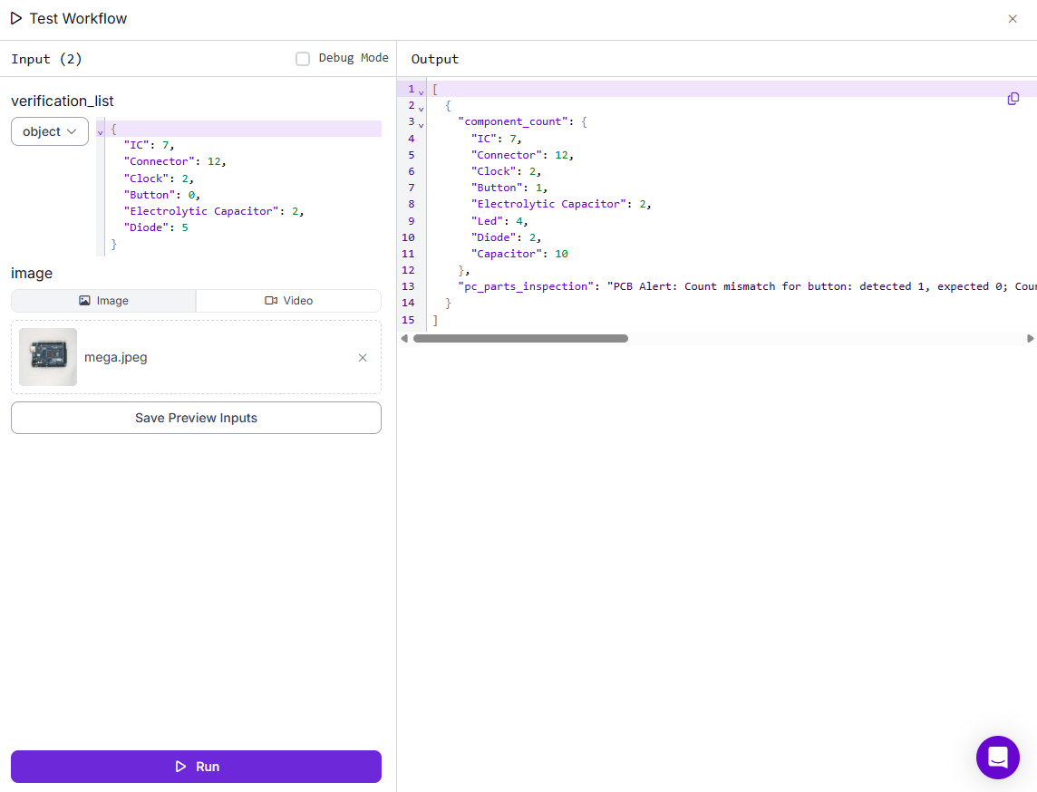
With following input verification list as the input along with image.
{
  "IC": 7,
  "Connector": 12,
  "Clock": 2,
  "Button": 0,
  "Electrolytic Capacitor": 2,
  "Diode": 5
}
This verification_list is a crucial input in the part inspection workflow as it defines the expected number of each component that should be present on the PCB. By passing this structured input to the custom Python block, the system can compare the actual detected counts from the object detection model against the expected values. This comparison allows the workflow to automatically verify whether the PCB is correctly assembled.
This list tells the system that a correctly assembled PCB should have 7 ICs, 12 connectors, 2 clocks, no buttons, 2 electrolytic capacitors, and 5 diodes. If any of these counts do not match the model’s detection output, such as missing a component, detecting extra parts, or identifying a component that shouldn't be there, the system can raise alerts accordingly. This ensures reliable and automated quality control during PCB manufacturing. With the above verification_list passed as input, the Workflow will return following output, accurately detecting missing, extra and foreign components.
{
    "component_count": {
      "IC": 7,
      "Connector": 12,
      "Clock": 2,
      "Button": 1,
      "Electrolytic Capacitor": 2,
      "Led": 4,
      "Diode": 2,
      "Capacitor": 10
    },
    "pc_parts_inspection": "PCB Alert: Count mismatch for button: detected 1, expected 0; Count mismatch for diode: detected 2, expected 5; Foreign component detected: led (count: 4); Foreign component detected: capacitor (count: 10); Total number of foreign components: 14"
  }
In this inspection result, the computer vision workflow compared the detected components on a PCB against the expected verification_list provided. The model correctly identified 7 ICs, 12 connectors, 2 clocks, and 2 electrolytic capacitors, matching the required counts. However, it also detected 1 button, even though none were expected, which indicates an extra or misplaced component. Additionally, only 2 diodes were found when 5 were required, meaning 3 diodes are missing. Beyond that, the system detected 4 LEDs and 10 capacitors, which were not part of the expected components list. These are flagged as foreign objects. In total, there are 14 unexpected components on the board. As a result, the system has raised an alert indicating mismatches in component counts and the presence of foreign parts, suggesting the PCB does not meet quality requirements and should be reviewed or rejected. Here’s the resultant image.
This workflow detects and counts PCB components using computer vision, then compares the results against an expected list. If any required parts are missing or unexpected components are found, it raises an alert. In the example, the workflow flagged the PCB due to a missing diode, an extra button, and the presence of foreign components like LEDs and capacitors.
Computer Vision For Part Inspection
Through this blog, we’ve explored how computer vision is revolutionizing part inspection in manufacturing by providing accurate, fast, and automated quality control. From detecting missing or extra parts to identifying defects, incorrect assemblies, and even color mismatches, computer vision systems ensure every product meets strict quality standards before reaching customers. We also demonstrated how to build a real-world part inspection system using Roboflow, custom Python logic, and object detection models, culminating in a smart PCB inspection workflow that detects mismatches and foreign components with precision. Get started free today.
This integration of AI into inspection workflows not only reduces human error and labor costs but also drives higher production efficiency and product reliability. As factories evolve into smart manufacturing hubs, computer vision will continue to play a pivotal role in ensuring zero-defect production.
Cite this Post
Use the following entry to cite this post in your research:
Timothy M. (May 7, 2025). Part Inspection Using Computer Vision. Roboflow Blog: https://blog.roboflow.com/part-inspection-using-computer-vision/