

You can detect scratches, crazing, pitting, rolled-in scale, patches, and inclusions on metal surfaces by fine-tuning RF-DETR. Then use a three-block Roboflow Workflow to draw a labeled bounding box around every defect it finds in a new image.
A small scratch on a piece of metal might not look like much. On a manufacturing line, however, that same scratch could mean a part needs to be rejected before it reaches the next stage of production. When thousands of parts are moving through a facility every day, inspecting each one manually can quickly become slow, inconsistent, and difficult to scale.
Computer vision provides a way to automate this process. By training an object detection model on examples of defective metal surfaces, we can build a system that can identify defects and determine where they appear in an image.
In this tutorial, we’ll use Roboflow to train an object detection model to detect different types of defects on metal surfaces. We’ll use a metal surface defect dataset from Roboflow Universe and use the trained model to identify and locate defects in new images.
What Are Metal Surface Defects?
Metal surfaces can develop imperfections during manufacturing and processing. These defects can range from small scratches and pits to larger areas of irregular texture or material buildup. Detecting these imperfections early is an important part of maintaining product quality, but inspecting large quantities of metal manually can be time-consuming and difficult to keep consistent.
For this project, we'll focus on six types of metal surface defects:
- Scratches: Long, narrow marks or grooves that appear across the surface of the metal.
- Crazing: A network of fine, irregular lines or cracks that form across the surface.
- Pitted Surface: Small depressions or cavities scattered across the metal surface.
- Rolled-in Scale: Areas of scale that become pressed or embedded into the metal during the rolling process.
- Patches: Irregular regions on the surface that have a noticeably different texture or appearance from the surrounding metal.
- Inclusion: Foreign material or impurities that become trapped within the metal during manufacturing.
Although these defects can look quite different from one another, some can be difficult to distinguish from normal variations in the metal's surface. This makes them a useful problem for computer vision, where a model can learn the visual patterns associated with each defect.
Building a Metal Defect Detection System
In this tutorial, we'll build a simple computer vision pipeline for inspecting metal surfaces for defects. We'll start with a dataset from Roboflow Universe, prepare it for training, and fine-tune an RF-DETR model to recognize the different types of defects. Once the model is trained, we'll connect it to a Roboflow Workflow so we can run it on new images and see the model's predictions in action.
By the end, the Workflow will identify each defect, draw a bounding box around it, and label it with the corresponding defect type.
Step 1: Log in to Roboflow
To get started, sign in to your Roboflow account. If you don't have an account yet, you can create one for free.

Step 2: Fork the Metal Defect Dataset
Instead of collecting and annotating thousands of metal surface images from scratch, we'll start with an existing dataset from Roboflow Universe. This gives us a set of labeled examples that we can use to train our model.
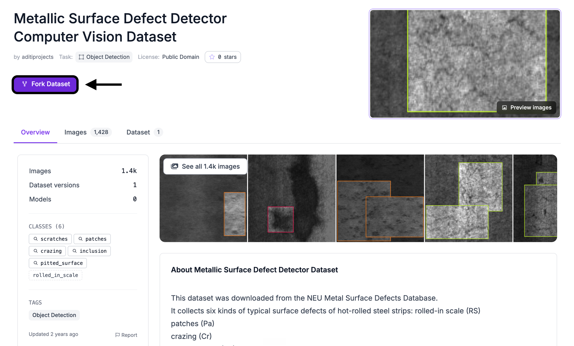
Open the Metallic Surface Defect Detector dataset in Roboflow Universe. The dataset contains 1,428 grayscale images across six defect classes: crazing, patches, pitted surface, inclusion, rolled-in scale, and scratches.
The dataset description uses these names to describe the different types of defects, while the corresponding annotation classes use slightly different names: crack, contamination, pitted_surface, inclusion, scale, and scratch. We will use the dataset's descriptive names when discussing the defects, while the annotation names will appear in the trained model's predictions and Workflow.
To use the dataset for training, click Fork Dataset in the top-left corner of the dataset page. Select the workspace where you want to store the dataset, then click Fork Dataset again.
Step 3: Train an RF-DETR Model
Now that the dataset is in your workspace, we can use it to train our object detection model. Open the project and select Train, then choose Custom Training as the training engine.
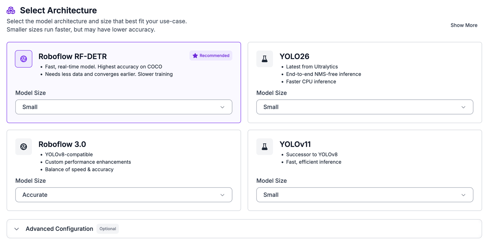
For the model architecture, select RF-DETR and choose the Small model size. RF-DETR is designed for real-time object detection and can be fine-tuned on custom datasets, making it a good choice for detecting and classifying surface defects.
Once training is complete, the model will be able to predict the location of a defect, its class, and a confidence score indicating how certain it is about each prediction.
Before starting the training run, Roboflow will also let us configure the dataset version, including the train, validation, and test splits as well as the preprocessing and augmentation settings.
Step 4: Set Up the Dataset Split
Before training, we need to divide the dataset into separate groups so we can train the model and evaluate how well it performs on images it hasn't seen before.
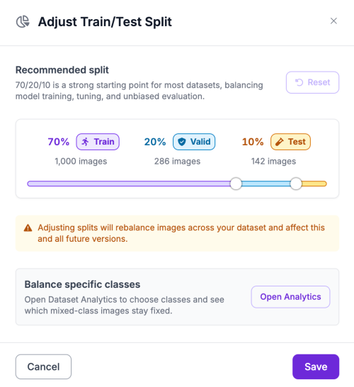
The training set contains the images the model learns from. The validation set is used during training to monitor how the model is performing on data outside of the training set. Finally, the test set is kept separate until the end and is used to measure the performance of the trained model.
For this project, we'll use the following split:
- 70% training
- 20% validation
- 10% testing
When creating your dataset version, check the split percentages and adjust them if needed before continuing.
Step 5: Configure Preprocessing and Augmentation
Before training the model, we need to prepare the images and introduce some variation into the training data. Roboflow provides preprocessing and augmentation tools that let us do this while keeping the original dataset unchanged.
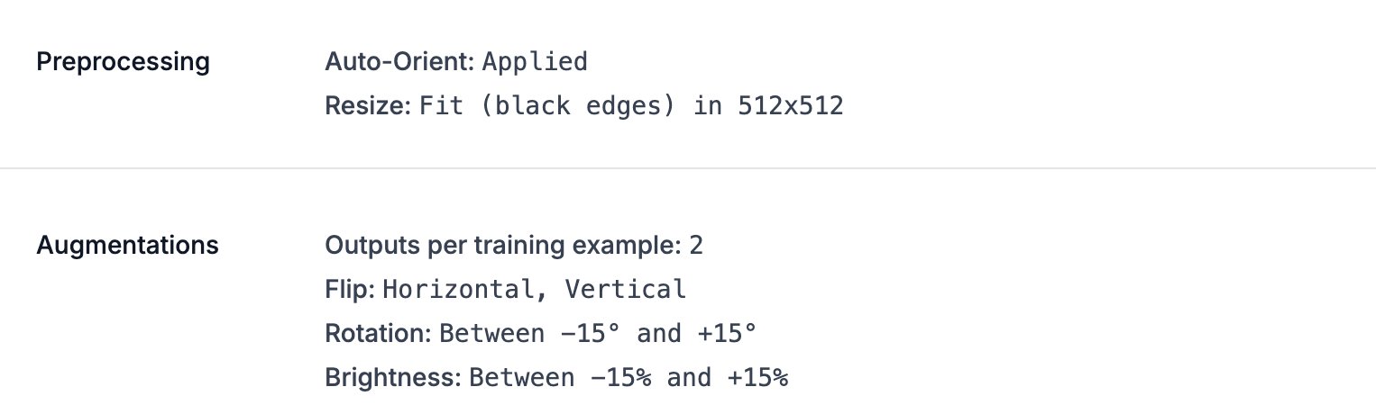
For preprocessing, use the following settings:
- Auto-Orient: Applied to ensure the images are correctly oriented.
- Resize: Set to 512 × 512 using Fit (black edges). This technique resizes the image while preserving its original aspect ratio, then fills any remaining space with black edges. We use this instead of stretching the image to 512 × 512 because stretching could distort the shape and appearance of defects such as cracks and scratches.
For augmentation, set Outputs per training example to 2. This creates additional variations of the training images using the following transformations:
- Flip: Enable both Horizontal and Vertical flips to help the model recognize defects regardless of their orientation.
- Rotation: Set between -15° and +15° to introduce small changes in the orientation of the metal surface.
- Brightness: Set between -15% and +15% to help the model handle differences in lighting conditions.
These augmentations add variation to the training images while keeping the important visual characteristics of the defects intact. This is particularly important for defects such as cracks and scratches, where changing the shape or appearance too much could make them harder for the model to learn.
Once the settings are configured, click Start Training to begin training the model.
Step 6: Evaluate the Model
Once training is complete, Roboflow evaluates the model on the validation set to give us an indication of how well it can detect defects on images that were not used to train the model.
For this training run, the model achieved the following results:
| Metric | Score |
|---|---|
| mAP@50 | 67.0% |
| Precision | 60.1% |
| Recall | 69.9% |
| F1 | 64.6% |
The model achieved an mAP@50 of 67.0%, meaning it was able to locate and classify the different types of metal surface defects with a moderate level of accuracy. The 60.1% precision indicates that some of the model's detections were incorrect, while the 69.9% recall shows that the model was able to identify a majority of the defects present in the validation images.
The 64.6% F1 score provides a balance between precision and recall, giving us another measure of the model's overall detection performance.
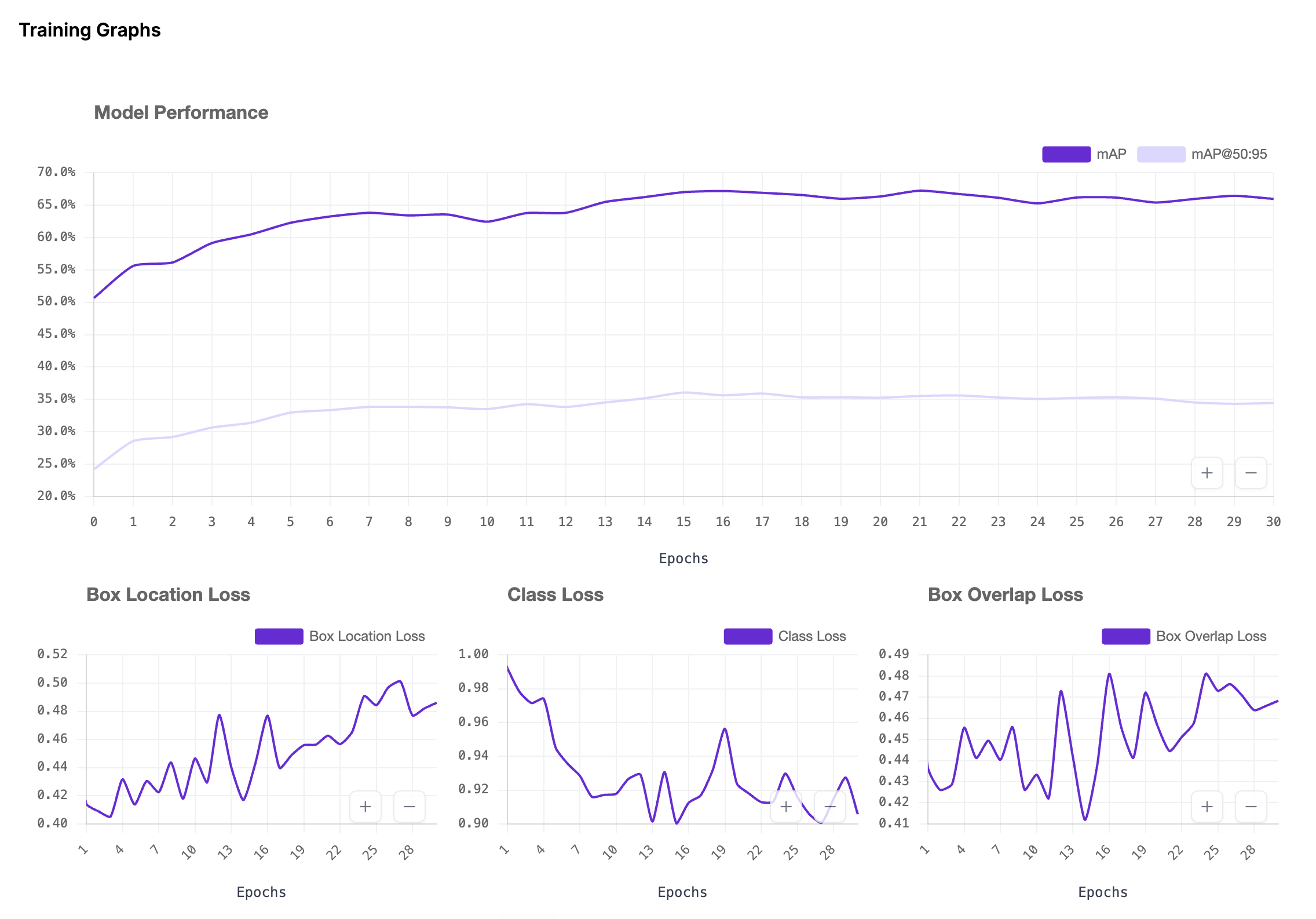
These results provide a useful starting point for demonstrating automated metal defect detection. However, the model could likely be improved further with additional training data, better representation of difficult defect types, or experimentation with different model and training configurations.
Step 7: Build the Metal Defect Detection Workflow
Now that we have a trained model, we can use a Roboflow Workflow to turn its predictions into a simple metal inspection pipeline. The Workflow will take an input image, run it through our RF-DETR model, and display the detected defects directly on the image.
To create the Workflow, open the Workflows tab in your Roboflow dashboard and select Create Workflow. Choose a blank Workflow. The Input and Output blocks will already be included.
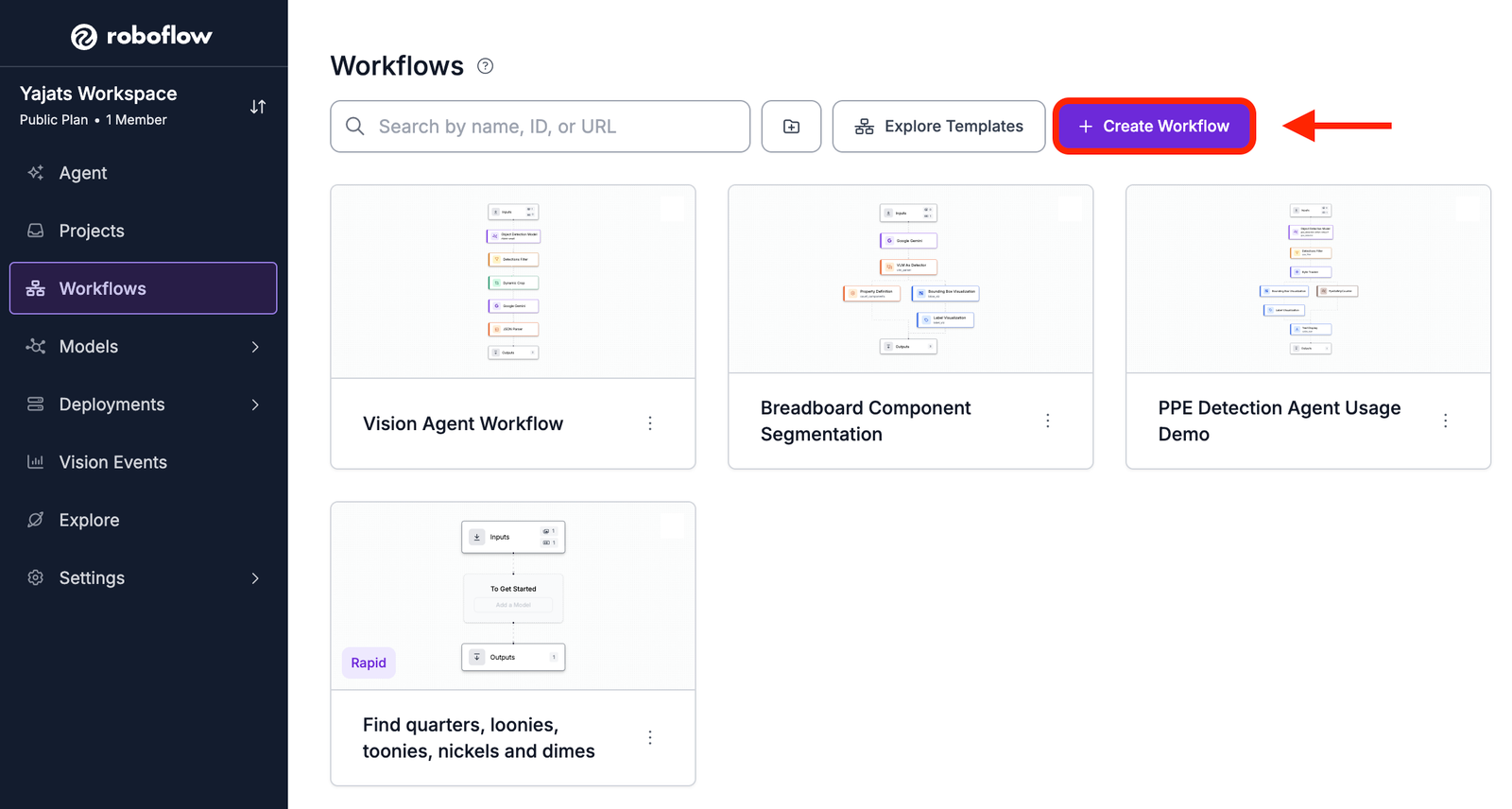
For this project, we'll use three blocks:
- Object Detection Model
- Bounding Box Visualization
- Label Visualization
The Object Detection Model block runs our trained RF-DETR model and produces the defect predictions. The visualization blocks then use those predictions to draw bounding boxes and display the corresponding defect classes on the image.
This gives us a straightforward way to take the model's predictions and turn them into an image that is easier to interpret during inspection.
Block 1: Object Detection Model
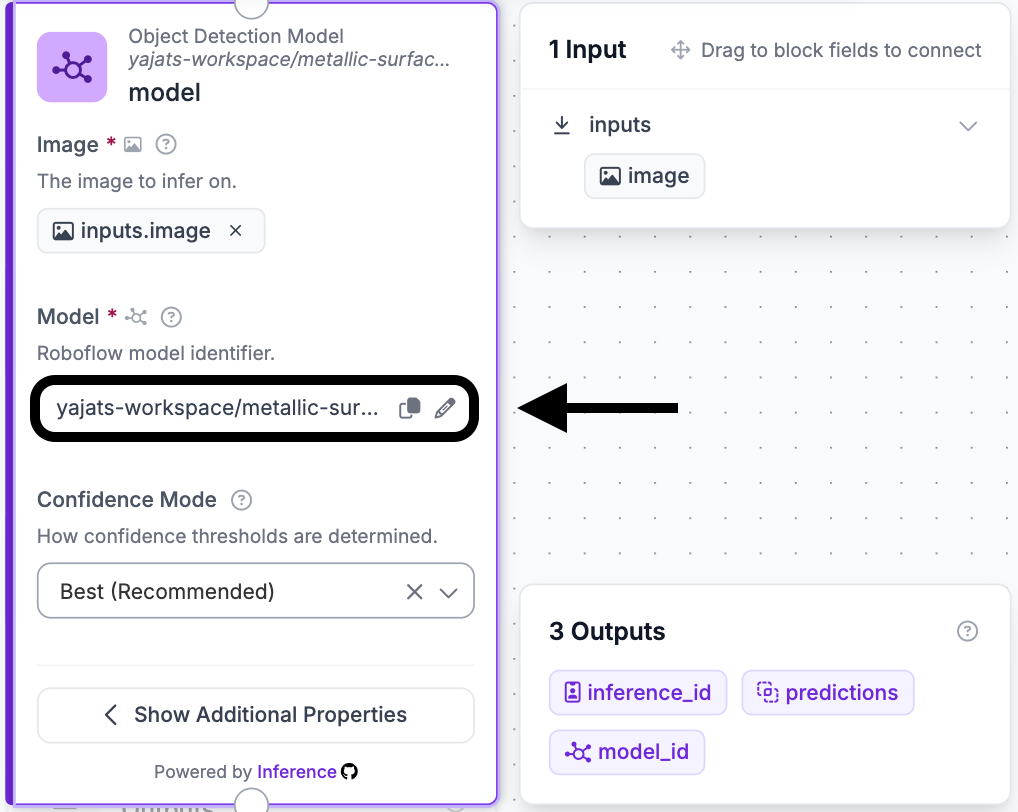
The first block we need is the Object Detection Model block. This is where our trained RF-DETR model will process the input image and identify any metal surface defects.
Click Add Block and search for Object Detection Model. Connect the block to the Image Input block, then select the RF-DETR model you trained earlier from the model dropdown.
Set the image input to use the image provided by the Workflow's Input block. You can also adjust the confidence threshold to control which predictions are passed through the rest of the Workflow. A higher threshold will filter out more low-confidence predictions, while a lower threshold will allow more detections through. We will use Best (Recommended) as the Confidence Mode for this tutorial. If you want to manually control the confidence threshold, change the Confidence Mode to Custom.
Block 2: Bounding Box Visualization
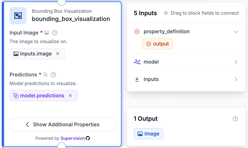
Next, we'll make the model's predictions visible by adding a Bounding Box Visualization block.
Click Add Block and search for Bounding Box Visualization. Connect it to the Object Detection Model block and configure it with:
- Image: The original image from the Input block
- Predictions: The predictions from the Object Detection Model
The block uses the coordinates produced by RF-DETR to draw a bounding box around each detected defect. This makes it easier to see exactly where the model believes a defect is located.
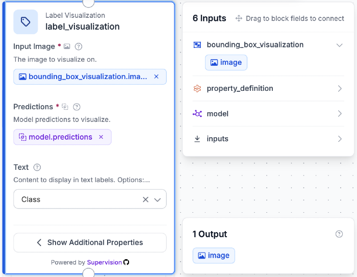
Block 3: Label Visualization
Finally, add a Label Visualization block to display the type of defect detected alongside each bounding box.
Connect it after the Bounding Box Visualization block and configure it with:
- Image: The output from Bounding Box Visualization
- Predictions: The predictions from the Object Detection Model
Set the label to display the predicted class name. Depending on the model's prediction, the output could identify a defect such as contamination, crack, inclusion, pitted_surface, scale, or scratch.
With this block in place, the final image will show both where each defect was detected and what type of defect the model believes it is.
Step 8: Test the Workflow
With the Workflow configured, the next step is to see how the model handles images it has not seen before.
In the Workflow editor, click Test in the upper-right corner and upload an image of a metal surface. After running the Workflow, Roboflow will pass the image through the trained RF-DETR model and return the visualized predictions.
The output should contain bounding boxes around the regions identified as defects, with a label indicating the predicted defect class. This gives us a quick way to check whether the model is identifying defects in the correct locations and assigning them to the appropriate classes.
Try running the Workflow on several different images rather than evaluating it from a single prediction. Images with different defect types, surface patterns, and appearances can give you a better sense of how consistently the model performs.
If you notice that the model is making predictions where no defect is present, increasing the confidence threshold in the Object Detection Model block can filter out some lower-confidence detections. Conversely, lowering the threshold can be useful if the model is consistently missing defects that are clearly visible.
Testing the Workflow this way gives us a practical look at how the trained model behaves outside of the training process and provides a starting point for identifying areas where the model could be improved.
You can try the complete metal defect detection Workflow here.
Metal Defect Detection Conclusion
Computer vision can make metal surface inspection faster and more consistent by automatically identifying defects in images. In this tutorial, we trained an RF-DETR model on a metal defect dataset and connected it to a Roboflow Workflow to detect and label defects on new images.
The model provides a useful starting point for automated inspection, but there is still room to improve its performance. A larger and more diverse dataset, better annotations, and additional training experimentation could help the model handle difficult defects more reliably.
The same approach could also be taken further by connecting the trained model to a live camera feed, allowing metal surfaces to be inspected automatically as they move through a production line.
Cite this Post
Use the following entry to cite this post in your research:
Yajat Mittal. (Jun 26, 2026). How to Detect Metal Defects with Computer Vision. Roboflow Blog: https://blog.roboflow.com/detect-metal-defects/