

You can build a ceramic defect detection system with Roboflow. Train Roboflow's RF-DETR Small, and wire the model into a Workflow that boxes and labels every hole, line, and edge chip in a new tile image.
A small crack, chip, or hole on a ceramic tile might not seem like a big deal at first. But when you're manufacturing thousands of tiles, letting even a small number of defective products make it through quality control can quickly become a costly problem.
With computer vision, cameras can continuously monitor tiles on a production line and automatically identify defects as they appear.
In this tutorial, we’ll build a ceramic tile defect detection system using Roboflow. We’ll use a dataset containing three common ceramic tile defects, train an object detection model to identify them, and evaluate how well the model performs. We’ll then use the trained model to detect defects in new ceramic tile images.
By the end, you’ll have a working computer vision pipeline that can automatically identify defects such as holes, lines, and edge chipping, and you’ll see how the same approach can be adapted for automated quality control in real-world manufacturing environments.
What Are Ceramic Defects?
Ceramic tiles can develop a variety of imperfections during manufacturing, whether from problems with the raw materials, the production process, or handling. These defects can affect the appearance and quality of a tile, making reliable quality inspection an important part of the manufacturing process.
In this project, we’ll focus on three common types of ceramic tile defects: holes, lines, and edge chipping.
Holes: Small openings or imperfections that appear on the surface of a tile. They can occur when air pockets or other irregularities form during the manufacturing process.
Lines: Visible linear marks or defects on the surface of the tile. Depending on the manufacturing process, these can appear in different shapes and sizes and may affect the finished appearance of the tile.
Edge chipping: Occurs when a portion of the tile's edge is broken or missing. Since tiles are often handled and transported throughout production, damaged edges can be a common quality issue.
While these defects can sometimes be identified through manual inspection, inspecting every tile by hand becomes difficult and time-consuming as production scales. This is where computer vision can help by automatically detecting and identifying defects as tiles move through the production process.
Building a Ceramic Defect Detection System
Now that we know what ceramic defects are, let's build a computer vision system that can automatically detect them. We'll use Roboflow to prepare our dataset, train an object detection model, and evaluate its performance on ceramic tile images it hasn't seen before.
Step 1: Log in to Roboflow
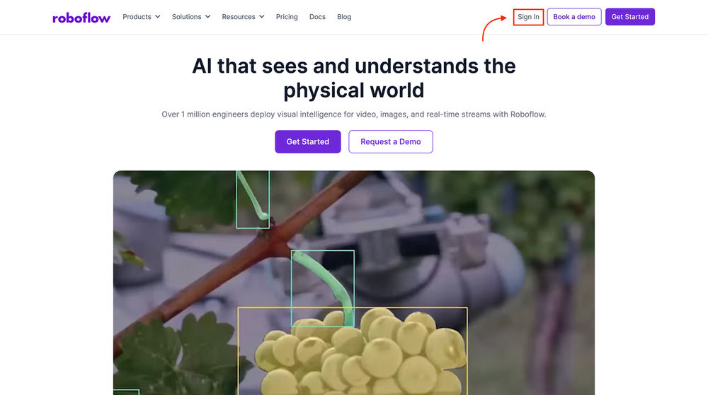
To begin, sign in to your Roboflow account. If you don't have an account yet, you can create one for free.
Step 2: Fork the Ceramic Tile Defect Dataset
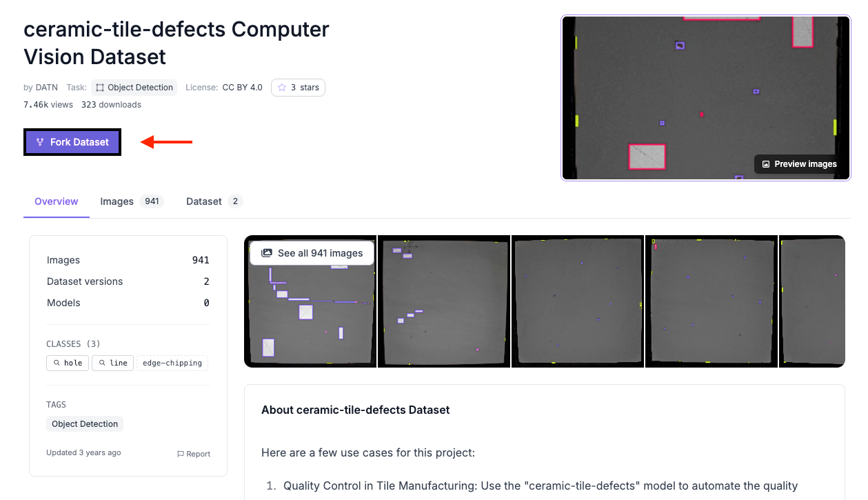
Rather than collecting and labeling ceramic tile images ourselves, we'll use an existing dataset from Roboflow Universe. Starting with a labeled dataset gives us the examples we need to train an object detection model without having to create the annotations from scratch.
Open the Ceramic Tile Defects dataset in Roboflow Universe. The dataset contains 941 images across three defect classes: hole, line, and edge-chipping.
To add the dataset to your workspace, click Fork Dataset in the top-left corner of the dataset page. Select the workspace where you want to use the dataset, then click Fork Dataset again.
Once the dataset has been forked, it will be available in your Roboflow workspace and ready for us to prepare for training.
Step 3: Train the RF-DETR Model
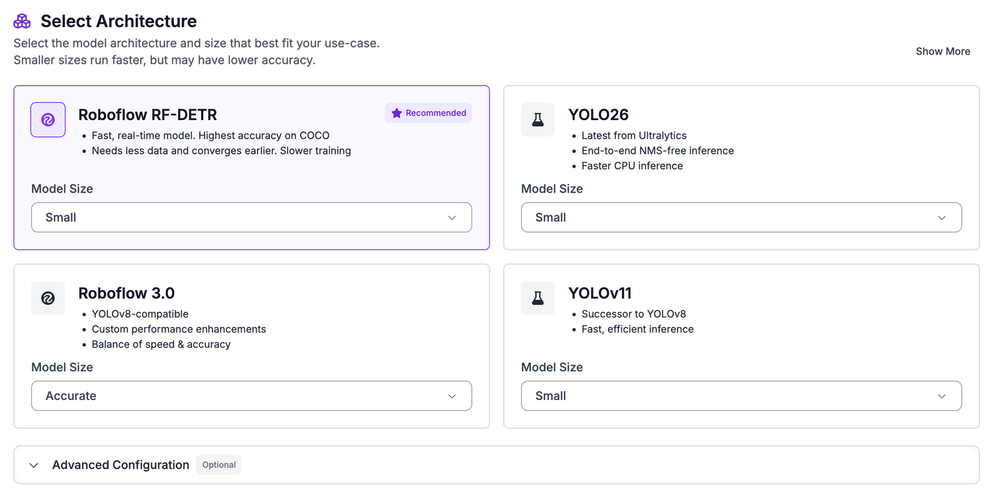
With the dataset added to our workspace, we're ready to train a model that can recognize the different ceramic tile defects. Open the project and select Train, then choose Custom Training as the training engine.
For the model architecture, select RF-DETR and choose the Small model size. RF-DETR is a real-time object detection model that can be fine-tuned on custom datasets, making it well suited for identifying and locating defects on ceramic tiles.
Before starting the training run, we'll configure the dataset version, including the image split, preprocessing, and augmentation settings. These settings determine how the images are prepared and what variations the model sees during training.
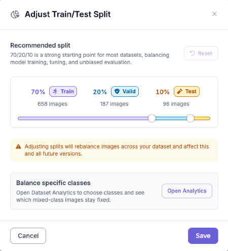
With the dataset in our workspace, we can now create a version that will be used for training. Roboflow lets us control how the images are divided so that we can train the model while still keeping separate images available for evaluating its performance.
Step 4: Set Up the Dataset Split
For this project, we'll use 70% of the images for training, 20% for validation, and 10% for testing. The training images are what the model learns from, while the validation images help us monitor its performance during training. The test images are kept separate and can be used to get a final measure of how the trained model performs on images it hasn't seen before.
Once the split is configured, we can move on to preparing the images with preprocessing and augmentation.
Step 5: Configure Preprocessing and Augmentation
With our dataset split in place, we can now prepare the images for training and introduce some variation into the examples the model will see. Roboflow lets us apply these changes when creating the dataset version, so the original images remain unchanged.
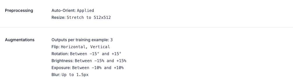
For preprocessing, use the following settings:
- Auto-Orient: Applied to make sure the images are consistently oriented before training.
- Resize: Set to 512 × 512 using Stretch to. This gives the model a consistent image size while keeping the entire ceramic tile in view. Keeping the full tile visible is particularly important for detecting edge chipping, which can occur along the boundaries of the image.
For augmentation, set Outputs per training example to 3. This generates additional variations of the training images using the following transformations:
- Flip: Enable both Horizontal and Vertical flips so the model can learn to recognize defects regardless of the tile's orientation.
- Rotation: Set between -15° and +15° to simulate small changes in how a tile may be positioned relative to the camera.
- Brightness: Set between -15% and +15% to help the model handle changes in lighting.
- Exposure: Set between -10% and +10% to introduce further variation in image brightness without significantly changing the appearance of the defects.
- Blur: Set to up to 1.5px to make the model more tolerant of slightly blurred images while keeping the defects visible.
These augmentations give the model more varied examples to learn from while keeping the visual characteristics of holes, lines, and edge chipping relatively consistent. We avoid more aggressive transformations because ceramic defects can be small and subtle, and excessive augmentation could make them harder for the model to recognize.
Once the settings are configured, click Start Training.
Step 6: Evaluate the Model
Once training is complete, Roboflow evaluates the model on the validation set to give us an idea of how well it performs on ceramic tile images it did not see during training.
For this training run, the model achieved an mAP@50 of 67.2%, with a precision of 73.7%, a recall of 63.6%, and an F1 score of 68.3%.
The 67.2% mAP@50 indicates how accurately the model was able to locate and classify the different ceramic tile defects. The model's 73.7% precision means that most of the defects it predicted were correct, while its 63.6% recall shows that it detected around two-thirds of the defects present in the validation images.
The 68.3% F1 score balances precision and recall, giving us another measure of the model's overall detection performance.
These results provide a useful baseline for our ceramic defect detection system. There is still room for improvement, particularly in helping the model detect defects that it currently misses. A larger and more diverse dataset, additional examples of difficult defects, or further experimentation with training settings could help improve its performance.
Step 7: Create the Ceramic Defect Detection Workflow
With our model trained, we can now use it to inspect new ceramic tile images. To do this, we'll create a Roboflow Workflow that takes an image as input, passes it through our trained RF-DETR model, and visualizes the detected defects.
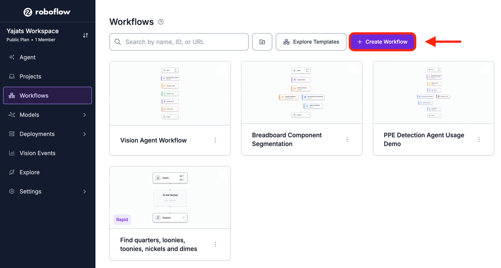
Open the Workflows tab in your Roboflow workspace and select Create Workflow. Start with a blank Workflow, which will give us an Input and Output block to work with.
For this project, we'll connect three main blocks between the input and output: an Object Detection Model block to run our trained model, a Bounding Box Visualization block to show where defects were found, and a Label Visualization block to identify the type of defect.
The resulting pipeline will take a ceramic tile image, run it through our trained model, and return an annotated image showing the detected holes, lines, and edge chipping.
Block 1: Object Detection Model
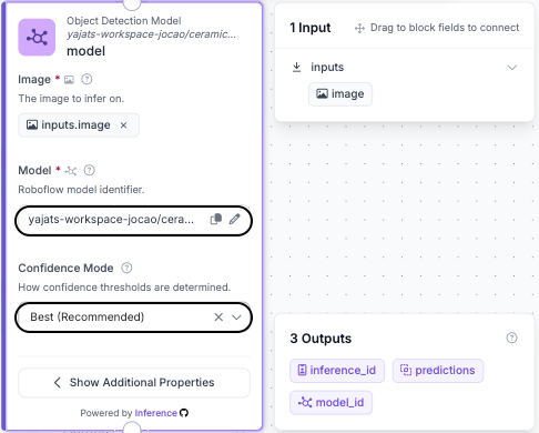
The first block we'll add is the Object Detection Model, which will run our trained RF-DETR model on the ceramic tile image.
Click Add Block and search for Object Detection Model. Connect the Image Input from the Input block to the model, then select the RF-DETR model we trained earlier.
The model will analyze the image and return predictions for any ceramic defects it finds, including the defect's location, class, and confidence score.
For Confidence Mode, we'll use Best (Recommended). This allows Roboflow to use the recommended confidence threshold for the model. If you want more control over which predictions are included, you can switch this setting to Custom and manually adjust the confidence threshold.
Block 2: Bounding Box Visualization
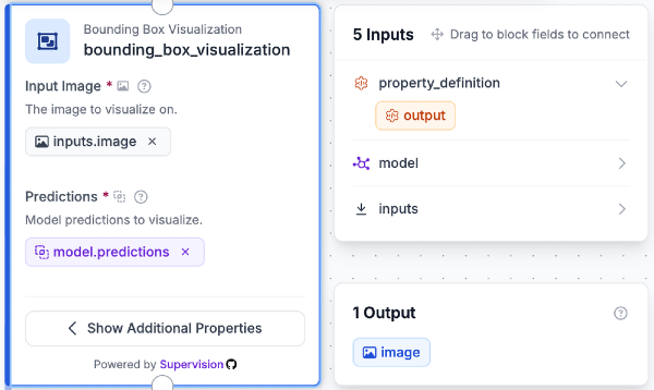
Once the model has generated its predictions, we need a way to see where those defects were detected. The Bounding Box Visualization block lets us display those predictions directly on the original tile image.
Add the Bounding Box Visualization block and connect it to the Object Detection Model. Set the image input to the original image from the Input block and use the model's predictions as the prediction input.
The Workflow will now draw a bounding box around each region that RF-DETR identifies as a defect. This makes it easier to visually check whether the model is finding the correct areas of the tile.
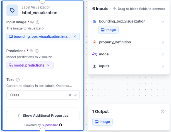
Block 3: Label Visualization
The final visualization block will tell us what type of defect was detected. Add a Label Visualization block and connect it to the Bounding Box Visualization block.
For the image input, use the output from the Bounding Box Visualization block, and connect the predictions from the Object Detection Model. The block will then display the predicted class alongside each detected region.
Depending on the model's prediction, the labels will identify defects as hole, line, or edge-chipping. With both visualization blocks connected, the final output will show the location and type of each defect detected by the model.
Step 8: Test the Workflow
Let's test the Workflow on a new ceramic tile image. In the Workflow editor, click Test in the upper-right corner and upload an image, then run the Workflow.
The output should display bounding boxes around any detected defects along with their predicted classes, such as hole, line, or edge-chipping.
Try a few different images to see how consistently the model detects each type of defect. If you notice too many incorrect detections or missed defects, you can adjust the confidence threshold in the Object Detection Model block.
You can try the complete Ceramic defect detection Workflow here.
Ceramic Defect Detection Conclusion
In this tutorial, we built a ceramic tile defect detection system using RF-DETR and a dataset containing examples of holes, lines, and edge chipping. We prepared the dataset, trained the model, and used a Roboflow Workflow to visualize its predictions on new tile images.
With more training data and additional examples covering different tile surfaces, lighting conditions, and defect appearances, the model could be further improved.
This same approach could be adapted for real-time quality inspection, where a camera monitors tiles on a production line and automatically identifies defective products before they reach the next stage of manufacturing.


Cite this Post
Use the following entry to cite this post in your research:
Yajat Mittal. (Aug 24, 2026). Ceramic Defect Detection with Computer Vision. Roboflow Blog: https://blog.roboflow.com/ceramic-defect-detection/