
In the U.S. alone, over 50,000 kitchen cutting injuries occur annually—nearly half during food preparation. Proper knife technique can reduce the risk of a cut by up to 50%.
With Roboflow’s robust keypoint detection capabilities, it is now easier than ever to create an internal tool to monitor cutting posture for your safety, efficiency, and your road to professional cuisine. With applications ranging from home kitchens to culinary schools, occupational safety, and even physical therapy, this AI-driven solution combines practical injury prevention with skill enhancement all within one seamless and self-contained workflow.
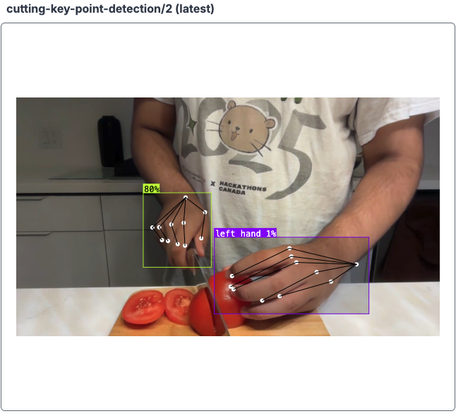
Live cutting tool demo
As you can see, there are keypoints on my hands and a little visual to display whether I'm cutting with good form or I need to fix it. Using the power of workflows and its visualization tools, this result is very easy to implement and replicable for different projects.
Let's dive in!
Train a Keypoint Detection Model
Head over to Roboflow and create an account and set up a personal workspace.
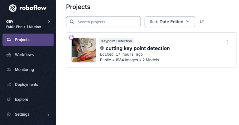
Next, go over to the projects tab and create a new keypoint detection project.
After you have created your project, we need to upload data with which we can train a model. Roboflow Universe has thousands of datasets and models you can access in your projects and workflows. But, since we're making an internal tool, the model we make would work best with data that we record ourselves. The data the model is trained on influences the data we test on to be similar if we want predictions to be made.
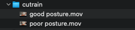
I recorded two different videos of cutting with good posture vs. cutting with bad posture. We can upload these videos and label frames in each as good or poor posture.
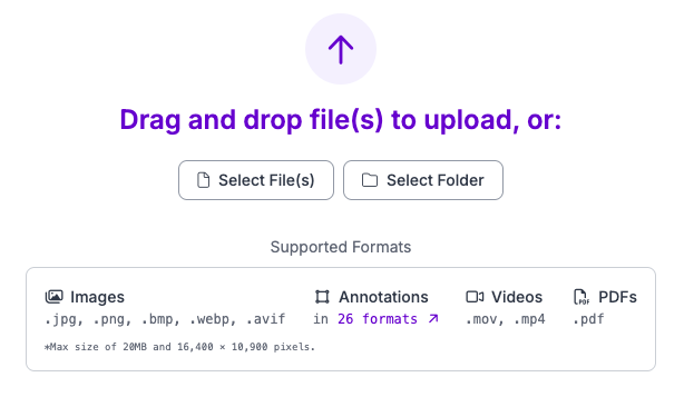
You can upload your data in the “upload data” section. Choose the framerate for all the frames extracted from the video. I found that 20-30 FPS yielded a large amount of frames, each being successive to allow for easy annotation.
Next, we need to label data so we can train a model that identifies key points associated with good and bad posture. If you aren’t sure how to do this, you can refer to this helpful guide, showing the process of making, annotating, and training a keypoint model.
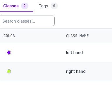
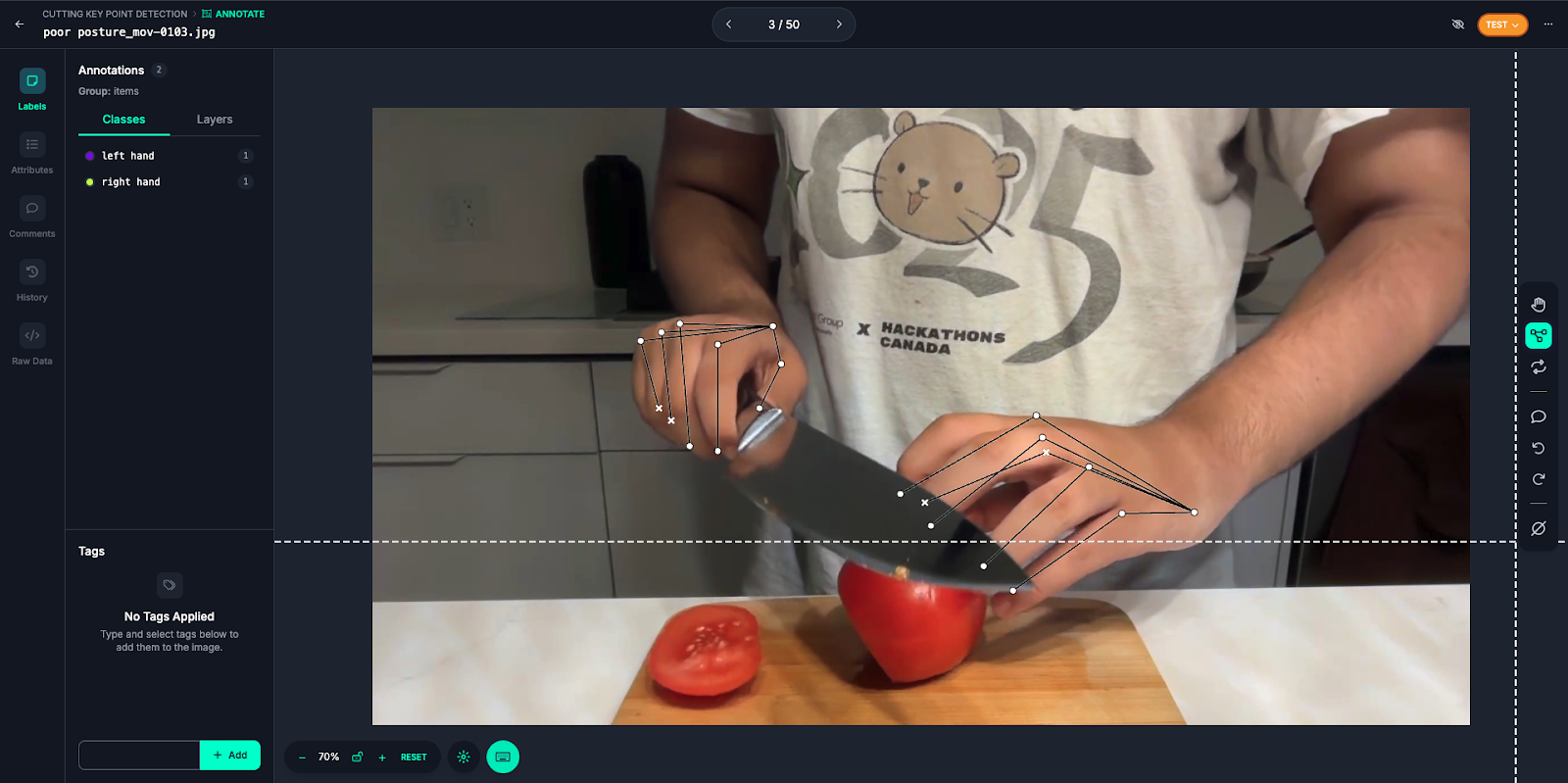
I’d like to show you how I’ll be annotating my images and the results after training. I set up two classes in the classes section for my left and right hands:
We need to create skeletons for our hands to later label in the annotation. Here are my skeletons and an example frame annotated with them. To learn more about labeling for keypoint detection, read our keypoint detection guide.
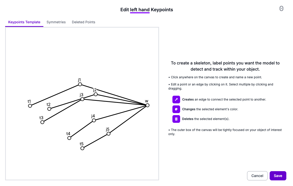
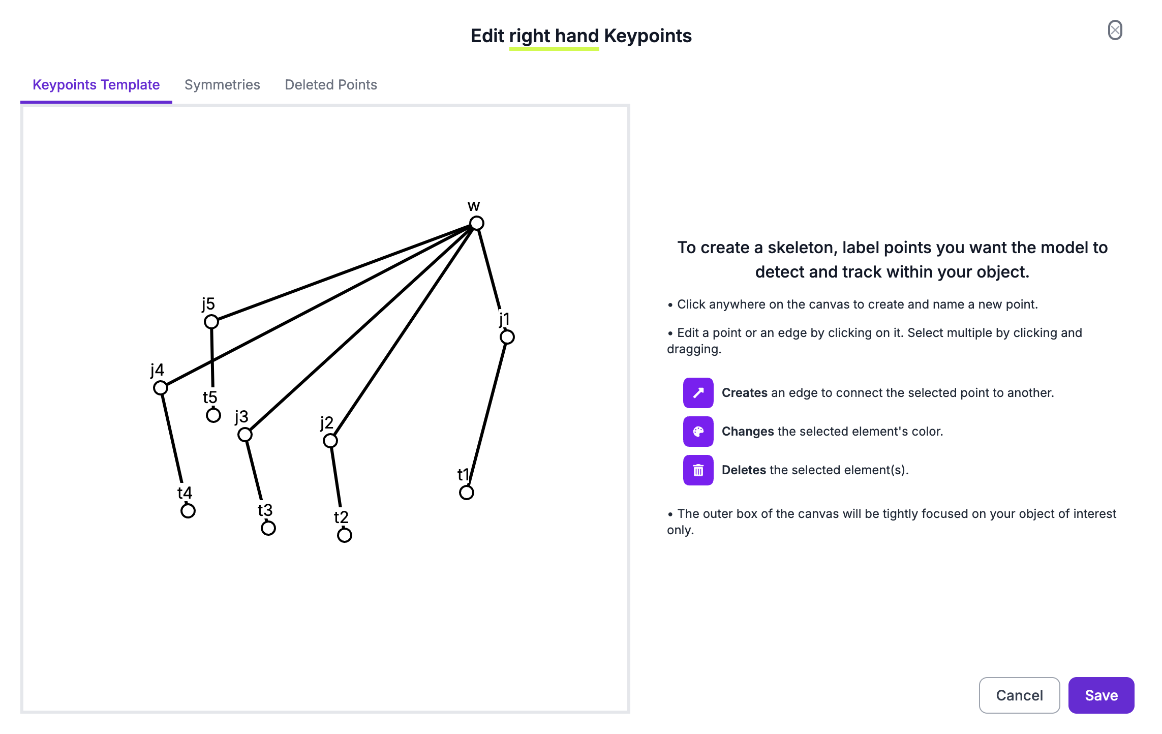
The “w”s stand for the wrist, “j”s for joints, and “t” for (finger) tips! It doesn’t really matter how you connect the points together, the edges are for your own understanding of the annotations. You can also label them however you’d like, in a way that makes sense to you.
I suggest labeling around 200 images, and then adding these images to the dataset. Then, you can custom train the model and apply a pre processing step of resizing and converting these images to greyscale during training.
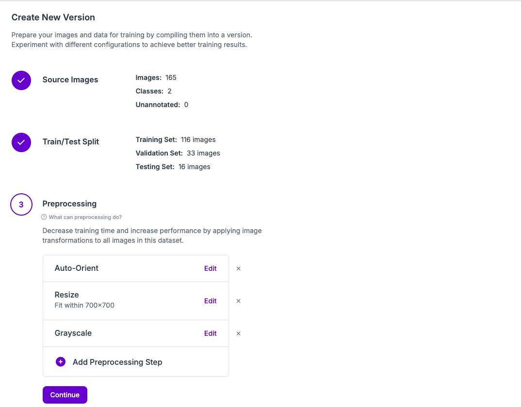
Applying these steps, especially the greyscale conversion, will help the model disregard colors when training, something that could potentially speed up training time and improve accuracy. Additionally, applying a brightness filter and augmentation of around 3-5x during training will give the model more data to work with.

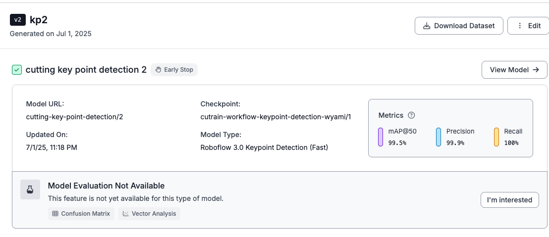
After training, the model should be able to make accurate predictions of the classes we labeled.
I strongly suggest referring to this guide again if you are unsure about the steps or the reasoning behind them. This will help you apply the keypoint model creation skills to any project you would want to make.
Once the model is working, we can start to build the tool with Workflows!
Create a Keypoint Visualization Workflow
One of Roboflow’s most efficient and useful features is Workflows. Workflows allow you to do a lot of cool stuff, such as chaining models together, getting visualizations, and executing custom code blocks in a pipeline to make complex models.
Head over to your workspace, click on the workflows tab, and create a new Workflow.
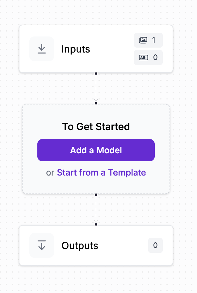
From here, we're going to add a series of blocks or “steps” that we want to be processed on the input image. Most definitely, we want to include the keypoint detection model we just created.
Add to workflow
You can then test your model in the model’s with the test workflow option. Keep in mind that you might need to adjust the confidence values and class filter in your keypoint model to get the results you want. In other words, if you're not getting predictions/bounding boxes, lower the confidence level. The keypoint confidence can be adjusted if your keypoints are inaccurate within the bounding boxes.

Next, attach a keypoint visualization block to the workflow.
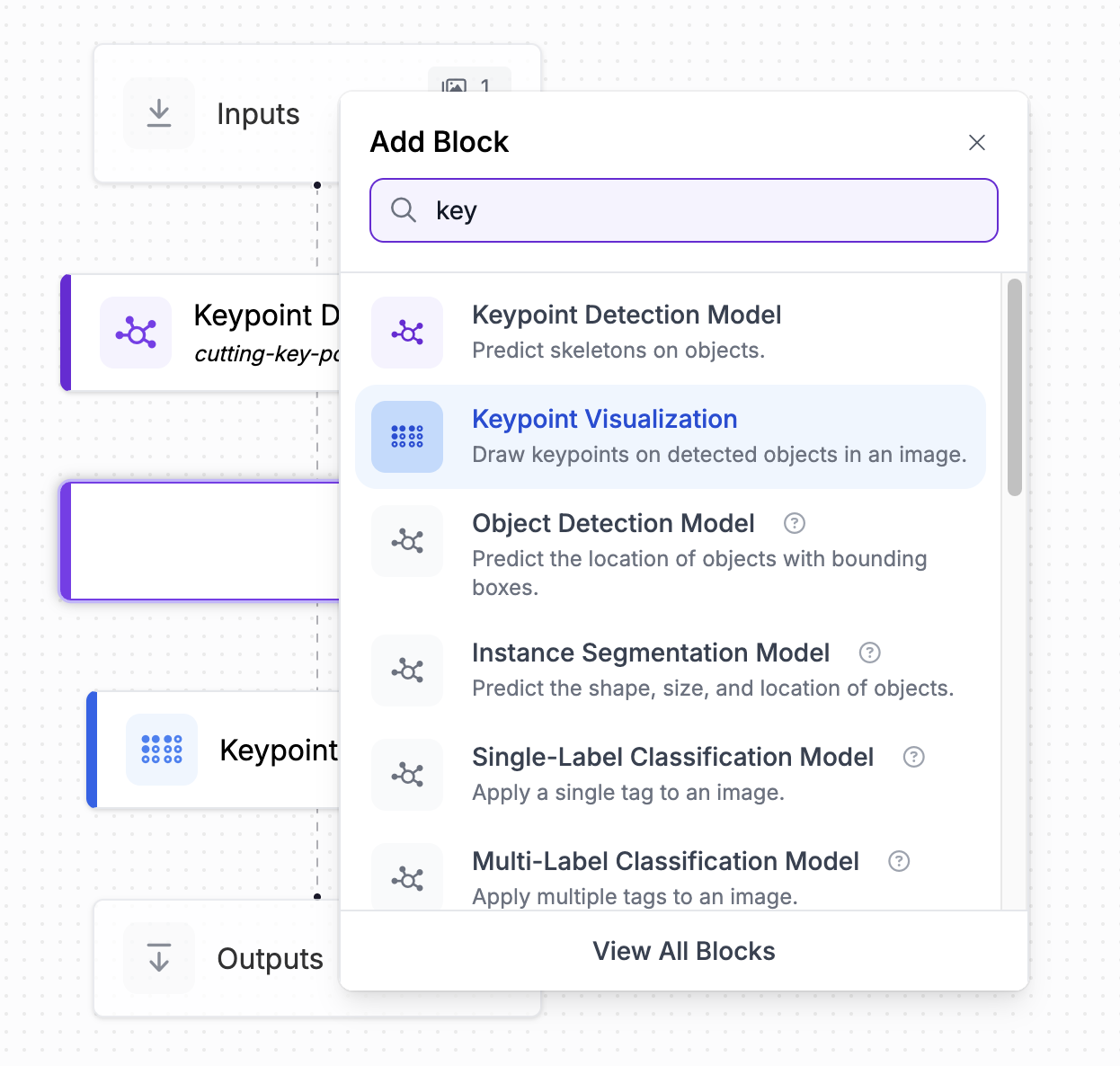
Roboflow has a variety of blocks you can add to your Workflows to do whatever you’d like. For this project, it would be great to see the complex predictions of key points the model makes on your own hands!
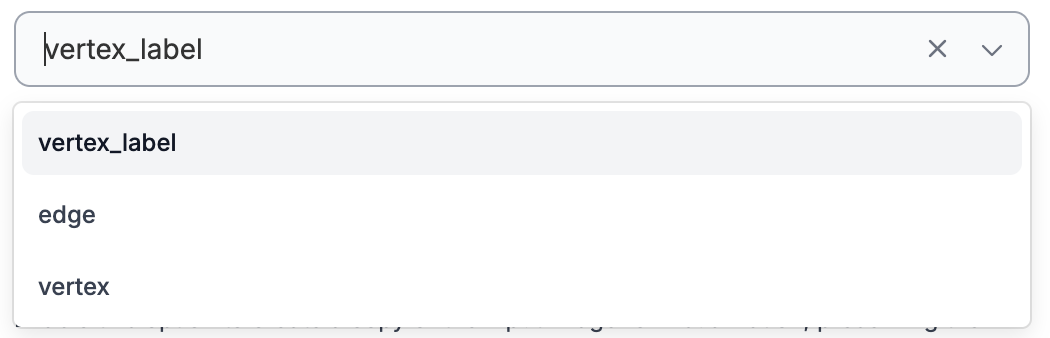
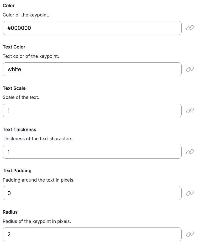
In the settings of the visualizer block, you can customize how you want the keypoints to be displayed. I chose to use the vertex_label visualizer. From there, there are some more settings to customize the final look.
From here, our workflow is complete with all the logic we need to detect keypoints and display them. You can test the workflow as well in case there are any issues.
Test the workflow
Use Inference Pipeline for Predictions on Livestream
Now, we are going to feed our live stream video that we were using to record the cutting. Open a code editor of your choice and create a new workspace/directory for this project.

Create a file called main.py, and head back over to the workflow we made in Roboflow. Using the deploy button and selecting the run on video setting.
Inference pipeline boilerplate
We’ll have to slightly modify this code. If you’re using your webcam, your video_reference should be 0 (internal webcam stream source). Otherwise, change it to the camera feed number you wish to use. Also, if you chose to hide your api key, workspace name, and workspace id as shown in the following code, you can follow this helpful guide.
from inference import InferencePipeline
import cv2
import os
from dotenv import load_dotenv

load_dotenv()

API_KEY = os.getenv("API_KEY")
WORKSPACE_NAME = os.getenv("WORKSPACE_NAME")
WORKFLOW_ID = os.getenv("WORKFLOW_ID")


# Process every frame
def my_sink(result, video_frame):
    if result.get("keypoint_visualization"):
        cv2.imshow("Workflow Image", result["keypoint_visualization"].numpy_image)


# Predict off live footage with inference pipeline
pipeline = InferencePipeline.init_with_workflow(
    api_key=API_KEY,
    workspace_name=WORKSPACE_NAME,
    workflow_id=WORKFLOW_ID,
    video_reference=0,
    max_fps=30,
    on_prediction=my_sink
)
pipeline.start()
pipeline.join()
This code, provided by Roboflow, is a use of the inference pipeline, allowing successive predictions to be made on livestreams very easily. Each prediction calls a my_sink function, and this is where the processing of each frame of video occurs.
Since we had a keypoint visualization block chained to the output, we can access the image it created by replacing the result.get(“output_image”) with result.get(“keypoint_visualization”), since that is what is actually stored in the result JSON from the block.
Changing it in the following line too will allow you to get live predictions of key points on your hands if you are cutting in the same spot with the same camera orientation!
The last processing step in our tool is actually determining if a given set of keypoints corresponds to a good posture or not!
Compute Vector Angles/Distances for Classification
Create another file called posture.py. This file will house the function that actually determines if a set of keypoints corresponds to good posture or not. Inside:
import math
import statistics

def distance(p1, p2):
    return math.hypot(p2[0] - p1[0], p2[1] - p1[1])

def is_posture_correct(predictions):

    # Labels for everything
    hand = max(predictions, key=lambda d: d["confidence"])
    kps  = {kp["class"]: (kp["x"], kp["y"]) for kp in hand["keypoints"]}

    w   = kps["w"]
    j1, t1 = kps["j1"], kps["t1"]
    j2, t2 = kps["j2"], kps["t2"]
    j3     = kps["j3"]
    j4, t4 = kps["j4"], kps["t4"]
    j5, t5 = kps["j5"], kps["t5"]

    # Palm angle relative to horizontal
    dx, dy     = j3[0] - w[0], j3[1] - w[1]
    palm_angle = abs(math.degrees(math.atan2(dy, dx)))

    # Extension ratios for thumb & index only
    ext_thumb = distance(t1, j1) / max(distance(j1, w), 1e-6)
    ext_index = distance(t2, j2) / max(distance(j2, w), 1e-6)

    # Grip openness (thumb to index)
    grip = distance(t1, t2)

    # Spread std dev
    joints = [j1, j2, j3, j4, j5]
    angles = [math.degrees(math.atan2(j[1]-w[1], j[0]-w[0])) for j in joints]
    spread_std = statistics.pstdev(angles)

    # Updated thresholds
    palm_ok      = 30 < palm_angle < 150
    extension_ok = 0.7 < ext_thumb < 1.3 and 0.7 < ext_index < 1.3
    grip_ok      = 50 < grip < 130
    spread_ok    = spread_std < 60

    return palm_ok and extension_ok and grip_ok and spread_ok
Many different measurements can be used to determine if a pose was valid or not, but this step requires a bit of trial and error. In the is_posture_correct function, I pass in the entirety of the models predictions, and then parse them to get the different points that I labeled.
After that, there were 2 primary factors I considered when determining if a pose was valid. The palm angle found with the delta between the third joint and wrist, and the arctan ratio. Then the extension between the thumb and the index, in which I create a distance function to make repetitive calculations easier.
Depending on how your model was trained and how accurate the key points are, you may need to consider different calculations for this step. Analyze your keypoint arrays and the visual, and make note of any common patterns you see. A helpful intermediate function you can implement is a distance function to save time when calculating the distance between two points.
Once you have a function for determining if the posture is correct or incorrect based on the keypoints, you can return it to the main file, and invoke it from the processing function!
from inference import InferencePipeline
from posture import is_posture_correct
import cv2
import os
from dotenv import load_dotenv

load_dotenv()

API_KEY = os.getenv("API_KEY")
WORKSPACE_NAME = os.getenv("WORKSPACE_NAME")
WORKFLOW_ID = os.getenv("WORKFLOW_ID")

def process(result, video_frame):
    frame = result["keypoint_visualization"].numpy_image

    predictions = result.get("predictions", [])
    correct_posture = is_posture_correct(predictions)
    print(correct_posture)

    cv2.imshow("Workflow Image", frame)
    if cv2.waitKey(1) & 0xFF == ord('q'):
        pipeline.terminate()

pipeline = InferencePipeline.init_with_workflow(
    api_key=API_KEY,
    workspace_name=WORKSPACE_NAME,
    workflow_id=WORKFLOW_ID,
    video_reference=0,
    max_fps=30,
    on_prediction=process
)

pipeline.start()
pipeline.join()
cv2.destroyAllWindows()
Display Visuals
With the verdict of whether the posture is correct or not, we can overlay a little visual to help users, on top of the overlaid keypoints.
Create another file in the directory called feedback.py, this file will take in the frame and if the posture with that frame is correct or not and display a visual in the top left before displaying it with cv2.
import cv2
import os

def display_feedback(correct_posture, frame):
    if correct_posture:
        cv2.putText(frame, "Keep going!", (30, 50), cv2.FONT_HERSHEY_SIMPLEX, 1.2, (0, 255, 0), 3, cv2.LINE_AA)
    else:
        cv2.putText(frame, "Fix posture!", (30, 50), cv2.FONT_HERSHEY_SIMPLEX, 1.2, (0, 0, 255), 3, cv2.LINE_AA)
Now, we can invoke this function from the processing function, to complete the tool!
from inference import InferencePipeline
from feedback import display_feedback
from posture import is_posture_correct  # Assuming your posture logic is in posture_check.py
import cv2
import os
from dotenv import load_dotenv

load_dotenv()

API_KEY = os.getenv("API_KEY")
WORKSPACE_NAME = os.getenv("WORKSPACE_NAME")
WORKFLOW_ID = os.getenv("WORKFLOW_ID")

pipeline = None

def process(result, video_frame):
    frame = result["keypoint_visualization"].numpy_image

    predictions = result.get("predictions", [])
    correct_posture = is_posture_correct(predictions)
    display_feedback(correct_posture, frame)

    cv2.imshow("Workflow Image", frame)
    if cv2.waitKey(1) & 0xFF == ord('q'):
        pipeline.terminate()

pipeline = InferencePipeline.init_with_workflow(
    api_key=API_KEY,
    workspace_name=WORKSPACE_NAME,
    workflow_id=WORKFLOW_ID,
    video_reference=0,
    max_fps=30,
    on_prediction=process
)

pipeline.start()
pipeline.join()
cv2.destroyAllWindows()
Be sure to define the pipeline variable so you can reference it in the processing function.
You can now run main.py and stay safe cutting!
Live cutting tool demo
Cite this Post
Use the following entry to cite this post in your research:
Aryan Vasudevan. (Jul 4, 2025). Creating a Cutting Safety Tool with Keypoint Detection. Roboflow Blog: https://blog.roboflow.com/cutting-safety-computer-vision/