
This tutorial builds a push-up counting system that combines computer vision with IoT hardware. An IoT camera node running on a Jetson Nano or Raspberry Pi uses a custom object detection model trained with Roboflow to classify two exercise states, push-up and push-down, then publishes each detected state to an MQTT broker over the internet. A JavaScript client subscribes to that broker, applies state-change logic to avoid double-counting, and displays the rep total in a web UI. The dataset and code are available on Roboflow Universe and GitHub.
With computer vision and Internet of Things (IoT) technology, you can build an application that tracks your performance in exercise. For example, you can count how many push ups you do. Such an automated counter allows you to track how far you are in your routine without manually keeping track.
In this blog post I will show how I made an exercise tracker project that uses the power of computer vision and IoT technologies to revolutionize your fitness routine.
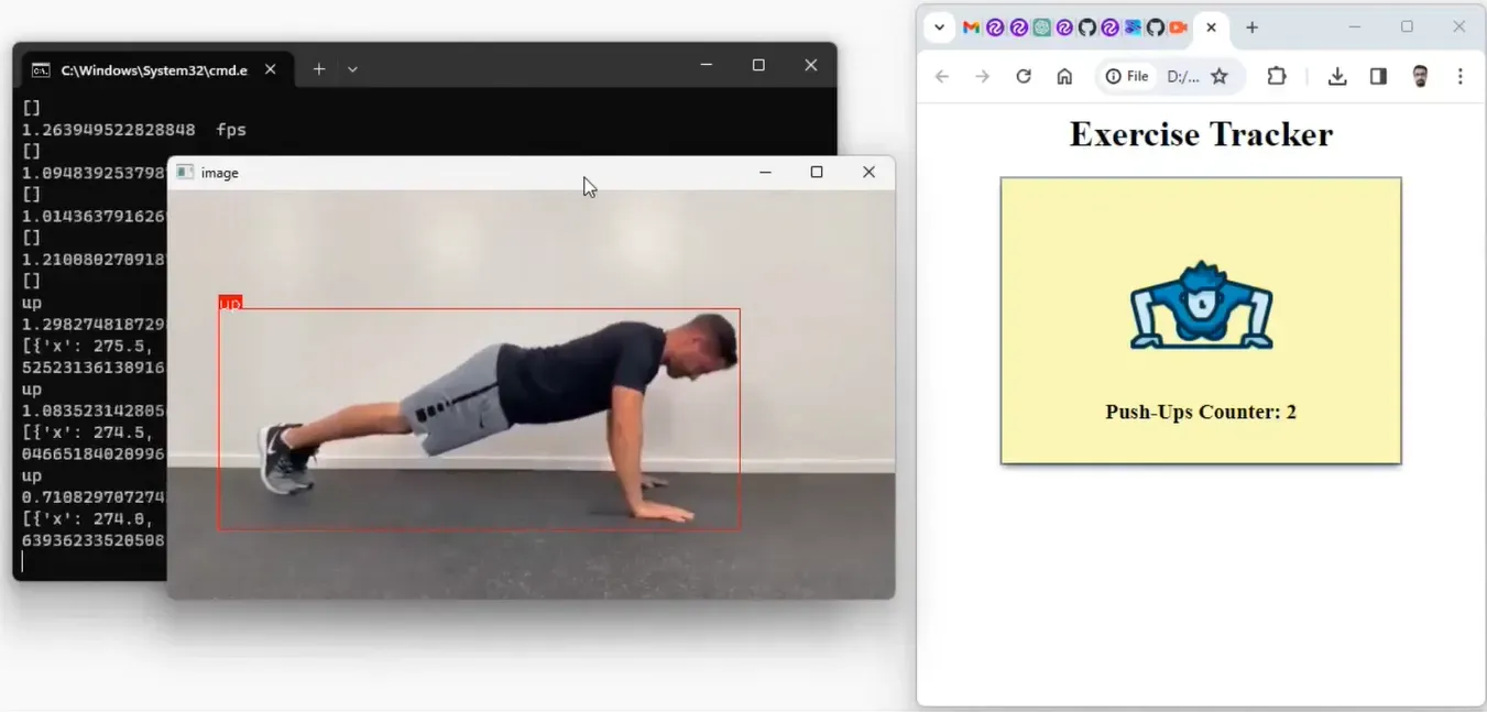
Here is a screenshot of the system in action:
How the Project Works
The exercise tracker system comprises an IoT sensor node with a camera-based setup capable of executing Roboflow’s Python SDK for inferencing. This sensor node captures exercise poses and uses an object detection model build with Roboflow platform to classify these poses. The detected pose is then published to an MQTT broker over the internet.
An application that is subscribed to the broker counts each pose detected by the JavaScript application. The exercise count is published in the web UI of the application to keep track of the exercise pose. The working of the system is represented in the following figure.
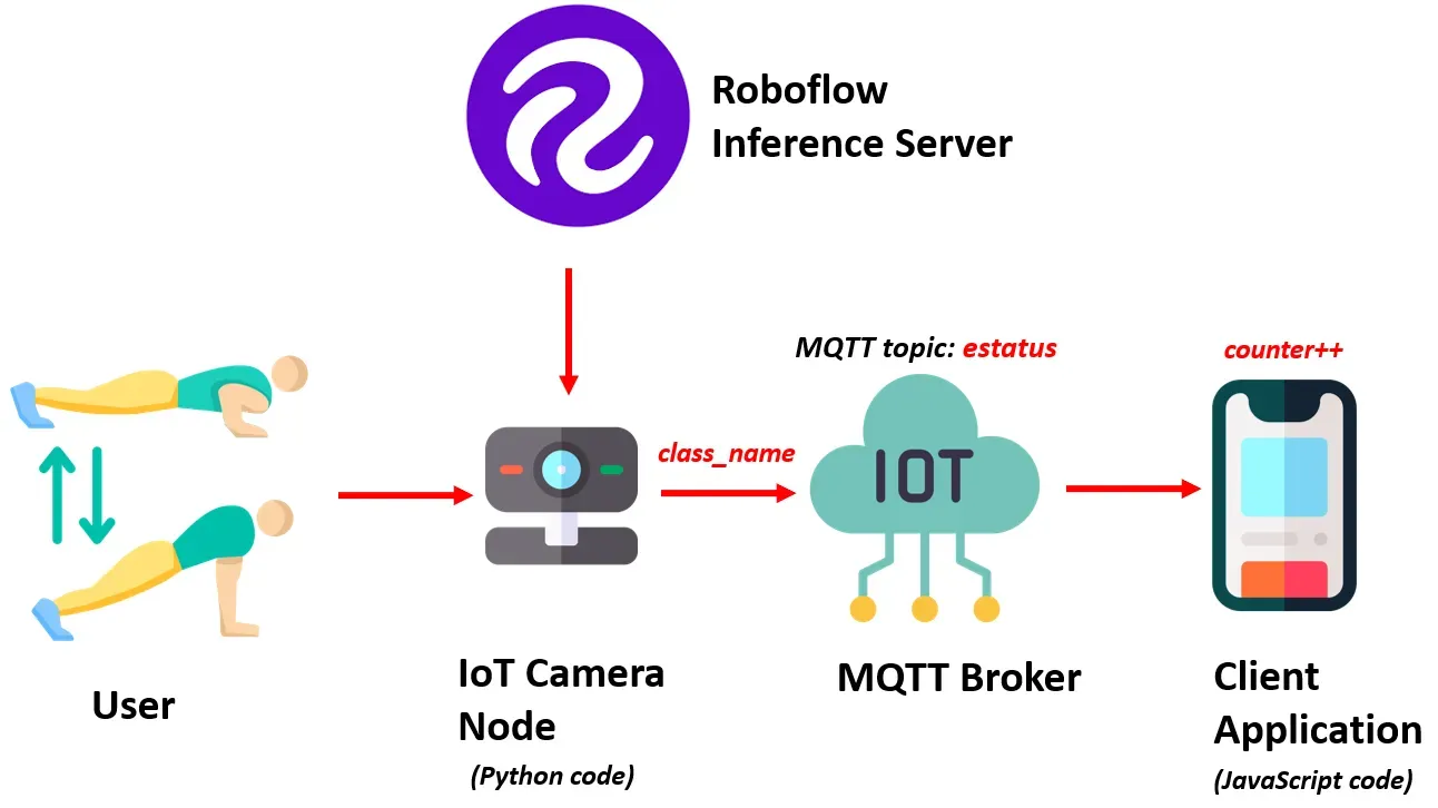
Using either Jetson Nano or Raspberry Pi, an IoT camera node uses a custom-built model from the Roboflow inference server to classify exercise poses. The result, extracted from the class_name variable, is then published to the MQTT topic estatus on the MQTT Broker.
Meanwhile, the client application, written in JavaScript, subscribes to the data on the estatus topic, calculates and stores the count in a counter variable, and presents the exercise pose count to the user on Web UI.
How the System is Developed
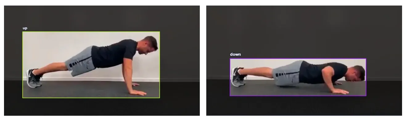
To effectively classify various exercise poses, such as push-ups in our example, we will use an object detection model. For this guide, we will focus on push ups. We will train an object detection model to identify one of two exercise states: 'push-up' and 'push-down.' These distinct states serve as the foundation for determining and calculating the push-up count.
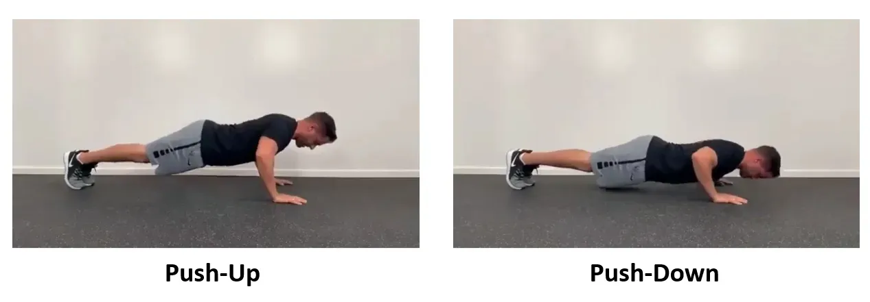
Fig 2: Push-Up and Push-Down states of the pose
Here are the steps used to develop the system:
- Collect and label a dataset
- Train an object detection model
- Run Inference to classify exercise pose and send result
- Write a JavaScript application to calculate and display the exercise pose count
Step #1: Collect and label a dataset
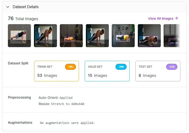
The image dataset for the push-ups exercise, encompassing the previously mentioned two distinct states, was collected manually, and uploaded to the Roboflow platform for labelling.
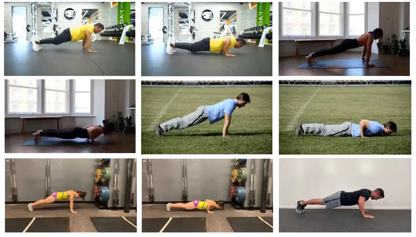
Each image has been labelled using bounding boxes to distinguish between the two classes: 'up' and 'down,' representing the 'push-up' and 'push-down' states of the pose, respectively.
Step #2: Train an object detection model
Upon completion of the labelling process, a dataset version is generated, and the model undergoes training using the Roboflow auto-training option.
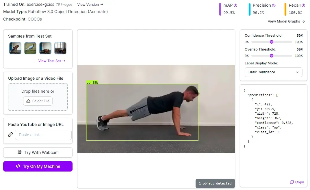
The training accuracy achieved is 99.5%.
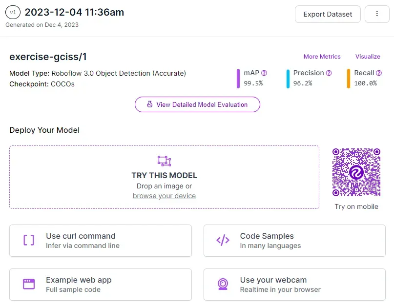
Once the model is trained, it is automatically deployed to a cloud API.
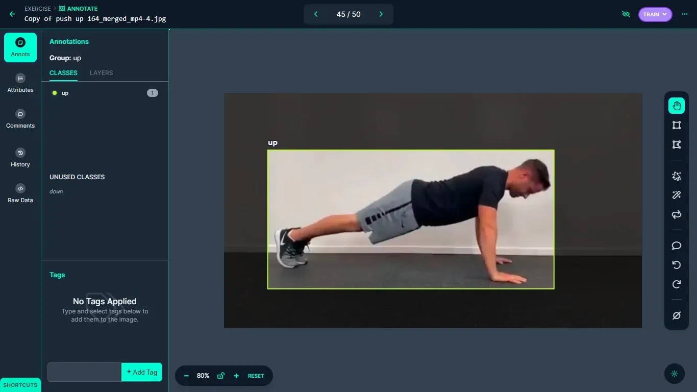
Roboflow offers a range of options for testing and deploying the model, including live testing in a web browser and deployment to edge devices. The following image shows the model tested using the Roboflow web interface.
Step #3: Detect exercise pose and send result over MQTT
In this project, the code sourced from the Roboflow GitHub repository is used to run inference via python script. The provided python code from Roboflow repository accepts a camera feed and processes video data from the camera through the trained model. To use the model, it is essential to populate the "roboflow_config.json" configuration file with specific values. These values include pertinent information about the model and an API key for authentication with Roboflow.
{
    "__comment1": "Obtain these values via Roboflow",
    "ROBOFLOW_API_KEY": "YOUR_API_KEY",
    "ROBOFLOW_WORKSPACE_ID": "tim-4ijf0",
    "ROBOFLOW_MODEL_ID": "exercise-gciss",
    "ROBOFLOW_VERSION_NUMBER": "1",
    "ROBOFLOW_SIZE": 640,
    "EMAIL": "YOUR_EMAIL",

    "__comment2": "The following are only needed for infer-async.py",
    "FRAMERATE": 24,
    "BUFFER": 0.5
}
The detection results from the Python script are broadcasted to an MQTT broker over the internet. We need to install the PAHO MQTT python library on the system in order to use it in the Python script that we are using. The library can be installed with the following command:
pip install paho-mqttAfter the MQTT library is installed, it can be included in our python code for object detection from Roboflow as follows:
import paho.mqtt.client as mqttThe next step is to specify the MQTT broker details and establish the connection as given in code below
broker_address="broker.hivemq.com"
port=1883

client = mqtt.Client("exer1") #create new instance
client.connect(broker_address, port) #connect to MQTT broker
For this guide, the free HiveMQ MQTT broker is used.
Then inside the infer() method use the following line of code to publish the name of the detected class to MQTT broker on the topic estatus.
client.publish("estatus", class_name) # publish detected class to MQTT BrokerThe updated infer() method from Roboflow code repository detects and classifies the exercise pose based on the trained model. The detected class stored in the class_name variable, which is sent to the MQTT broker. Running the Python code displays the following output:
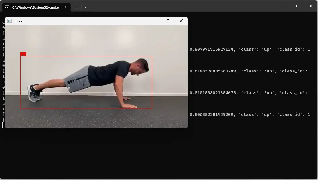
The data is sent to the MQTT broker in the background.
Step #4: Calculate and display the exercise pose count
In this step we build a simple JavaScript application that uses PAHO MQTT JavaScript library to connect to MQTT broker and subscribe to the MQTT topic estatus.
The PAHO MQTT library for JavaScript can be included in a HTML document with following code:
<script src="https://cdnjs.cloudflare.com/ajax/libs/paho-mqtt/1.0.1/mqttws31.min.js" type="text/javascript"></script>Next, we can define the UI to display the result as given in code below:
<div id="status">
  <img src="push-up.png" style="width:50%">
  <h3 id="msg">NA</h3>
</div>
Then, we can establish a connection to the broker:
client = new Paho.MQTT.Client("broker.hivemq.com", 8000 ,"exercie-client-001");After this, we subscribe to the topic estatus on which the Object Detection python code from Roboflow repository publishes the result of the detected class from variable class_name.
function onConnect() {
 client.subscribe("estatus");
}
Finally, we can write code to keep track of the count of the push-ups. In the following code a counter will be incremented on ‘up’ class for the ‘push-up’ pose.
function onMessageArrived(message) {
  if (message.payloadString === "down") {
     upMessageProcessed = false; // Reset the flag when the message is "down"
  } else if (message.payloadString === "up" && !upMessageProcessed) {
    // Increment the counter only once when the message is "up"
    counter++;
    document.getElementById("msg").innerHTML = "Push-Ups Counter: " + counter;
    upMessageProcessed = true; // Set the flag to true after incrementing the counter
  }
}
We increment the counter only when a class (e.g., 'up') is initially detected. The counter variable is then updated if the same class is detected again after the detection of another class (e.g., 'down')
In the code above, the counter increments only once until the next change in the detection result is reported. The counter will only increment one for the ‘up’ message until the next change is reported. This ensures the counter doesn’t increment with each prediction. Incrementing the counter with each prediction would be problematic because 10 `up` detections in a row would increment the counter 10 times, even if there was no `down` message
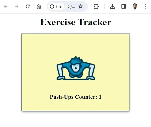
The upMessageProcessed flag ensures that the counter is not incremented again for ‘up’ message until after a ‘down’ message is received. The following will be the output when we run the code.

Conclusion
In this project we have implemented a computer vision pipeline to monitor and track exercise poses for Push-Ups exercise. Similar techniques can also be implemented for other types of exercises.
With the help of object detection results from our computer vision model, the project accurately extracts information about the exercise poses and publishes the results of the detected pose on an MQTT broker over the internet JavaScript logic is used to calculate the pose counts. These counts are displayed on a web interface
The potential applications of this exercise tracking system are vast, ranging from personalized fitness training to remote monitoring of workout sessions.
All code for this project is available at GitHub. The dataset used for this project is available on Roboflow Universe.
Cite this Post
Use the following entry to cite this post in your research:
Timothy M. (Dec 28, 2023). Building an IoT-Powered Exercise Tracker with Computer Vision. Roboflow Blog: https://blog.roboflow.com/exercise-tracking/