

To measure volume with computer vision, segment the object, convert its pixel dimensions to real units using a calibration marker of known size, then supply the third dimension from a known height, the object's shape, depth data, or a container's fill level. Roboflow Workflows lets you build this end to end without training a model: SAM 3 segments the object from a text prompt, the Mask Area Measurement block computes its pixel area, and a Custom Python block applies the calibration and volume formula. The example in this tutorial uses a 5 × 5 cm marker to return a box's length, width, external volume, and internal volume in centimeters.
Measuring the dimensions or volume of an object normally requires a ruler, tape measure, displacement method, or another physical measurement tool. In applications where many objects need to be measured repeatedly, doing this manually can be slow and difficult to scale.
Computer vision can automate this process using cameras and software. This can be useful in packaging, manufacturing, logistics, agriculture, and other environments where object size or material volume needs to be measured as part of an automated process.
In this tutorial, we will first look at the main ways computer vision can be used for volume measurement. Then, we will build a practical example in Roboflow Workflows using SAM 3 segmentation, Mask Area Measurement, physical calibration, and Custom Python to calculate the volume of a rectangular box.
So let's get started!
What Is Computer Vision Volume Measurement?
Volume is the amount of three-dimensional space that an object or material occupies. Computer vision volume measurement means estimating that quantity from camera images instead of measuring or weighing the item physically.
A vision system first locates and outlines the object or material in the image, usually through segmentation, which gives its boundary rather than just its identity. Those pixel measurements are then converted into real-world units such as centimeters or meters through calibration. Because an image records only two dimensions, the third has to be supplied separately, and how that is done defines the different methods described below.
The result is expressed in cubic units such as cm³ or m³, or in equivalent capacity units such as litres. In simple terms, it turns what a camera sees into a number describing how much space something takes up.
Methods for Measuring Volume with Computer Vision
Volume requires information about an object's three-dimensional size. Depending on the application, this information can come from known dimensions, the object's geometric shape, depth information, or its fill level. Computer vision can then measure or estimate the required dimensions and use them to calculate volume. The following are some practical ways to do this.
Use a Known Height
If the object's height is already known, computer vision only needs to measure its length and width. For example, suppose a camera measures a rectangular box as 40 cm × 30 cm, and the box height is known to be 20 cm then,
V = 40 X 30 X 20 = 24,000 cm³This is one of the simplest methods and works well for standard boxes, packages, sheets, and other objects with fixed dimensions.
Use the Object's Shape
If an object has a known geometric shape, you can measure only the dimensions required by its volume formula. For example:
- Rectangular box: A shipping carton or storage box can be treated as a rectangular solid. Measure its length, width, and height.
- Cube: A cube-shaped package or storage block has equal sides, so measuring one side is enough.
- Cylinder: A drum, can, pipe, or bottle can often be approximated as a cylinder. Measure its radius and height.
- Sphere: A ball or nearly spherical fruit can be approximated as a sphere. Measure its radius.
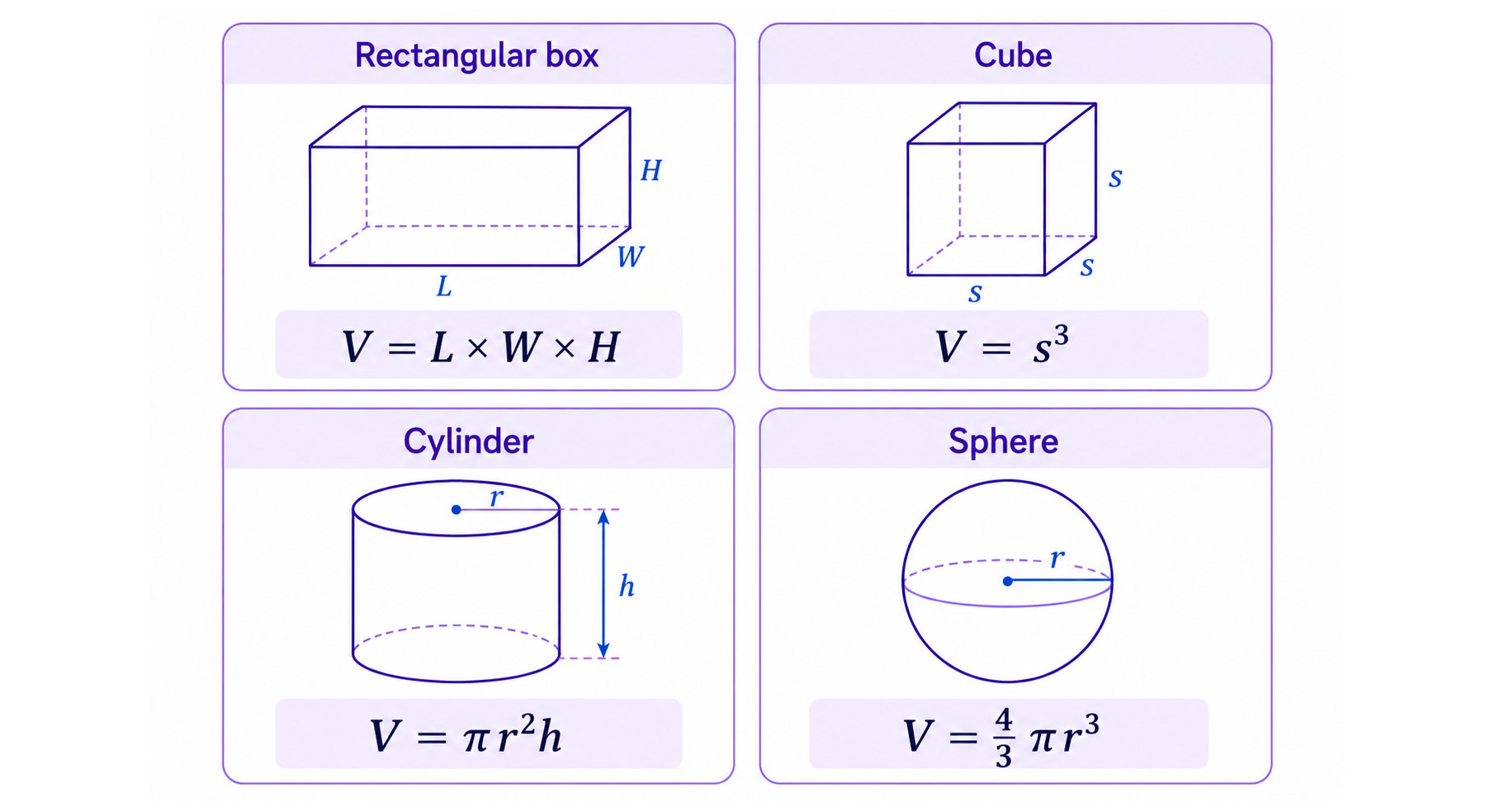
This works well when the object closely matches the assumed shape.
Use Depth Information
Depth information can come from a depth camera or a depth-estimation model. It is useful for irregular objects such as piles of gravel, grain, soil, food, or loose materials, where the height changes across the object. A depth camera can measure physical distance directly. For example, if the floor is 5 m from the camera and one point on a gravel pile is 3.8 m away, the pile is 1.2 m high at that point:
5.0 - 3.8 = 1.2 mThe system can first segment the pile to identify the area it covers and then measure its height at many points. These measurements can be combined to estimate the total volume. A depth-estimation model can also generate a depth map from a normal RGB image. Models such as Depth Anything V2 or V3 estimate which parts of the scene are closer or farther away. However, relative depth values are not automatically physical measurements such as meters, so additional calibration is needed when calculating real-world volume. Depth information can also be used to automatically determine an object's height instead of supplying a known height manually as stated in above sections.
Estimate Volume from Fill Level
For containers such as bins and tanks, computer vision can estimate how full the container is instead of measuring the material itself. For example, if a 240 L rectangular bin is estimated to be 60% full, the approximate material volume is:
240 X 0.60 = 144 LA camera can estimate the fill level by locating the material surface relative to the known height of the container. Research has demonstrated this using both RGB-camera-based fill-level detection and image-based liquid-volume measurement. For containers with a constant cross-section, such as a vertical rectangular bin or cylindrical tank, fill-height percentage corresponds directly to volume percentage. For containers whose width changes with height, such as tapered tanks or bottles, a geometric model or calibration curve is needed to convert fill height into volume.
How to Measure Box Volume with Computer Vision using Roboflow Workflows
The Box Volume Measurement Workflow measures the physical dimensions, top area, and volume of a closed rectangular box from a top-down image. The Workflow combines:
- SAM 3 instance segmentation to identify and outline the box.
- A known
5 × 5 cmblue calibration marker to convert pixel measurements into centimeters. - Mask Area Measurement block to calculate mask-level pixel area.
- A custom Python block using OpenCV, NumPy, and Supervision to:
- Detect the calibration marker.
- Measure box length and width.
- Apply the supplied box height.
- Calculate external and internal dimensions.
- Calculate external and internal footprint areas.
- Calculate external and internal volumes.
- Render the results on the output image.
The current Workflow is configured for:
| Parameter | Value |
|---|---|
| Calibration marker | 5 × 5 cm |
| Marker area | 25 cm² |
| External box height | 5.0 cm |
| Wall thickness | 0.2 cm |
| Box construction | Closed box |
The example assumes a rectangular closed box (14.0 cm x 13.6 cm ) with a known external height of 5 cm and wall thickness of 0.2 cm. Also a known 5 cm × 5 cm square card for physical calibration.
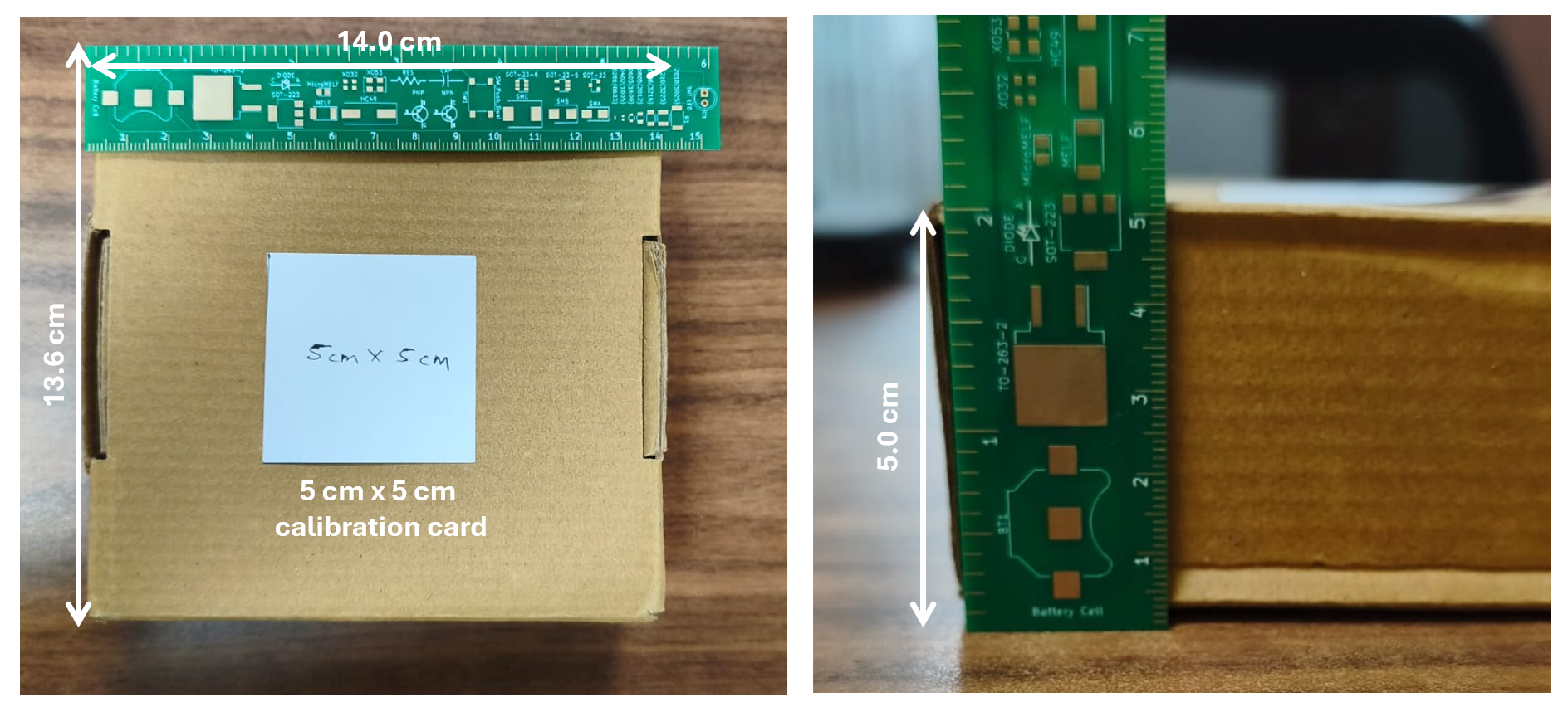
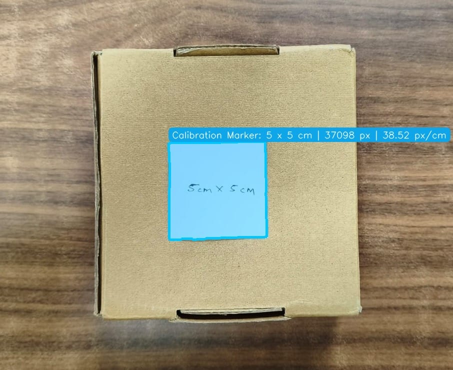
The image should be captured from directly above, with the camera approximately parallel to the top surface. The input image should look like following.
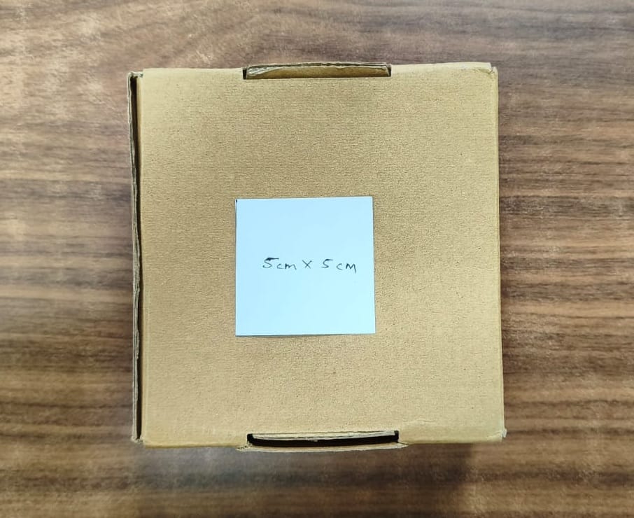
The calibration marker should be positioned on the same physical plane as the top surface being measured. If the marker and box surface are at significantly different heights, perspective can change their apparent sizes and produce an incorrect scale.
Workflow Structure
The Workflow processes each image in the following order:
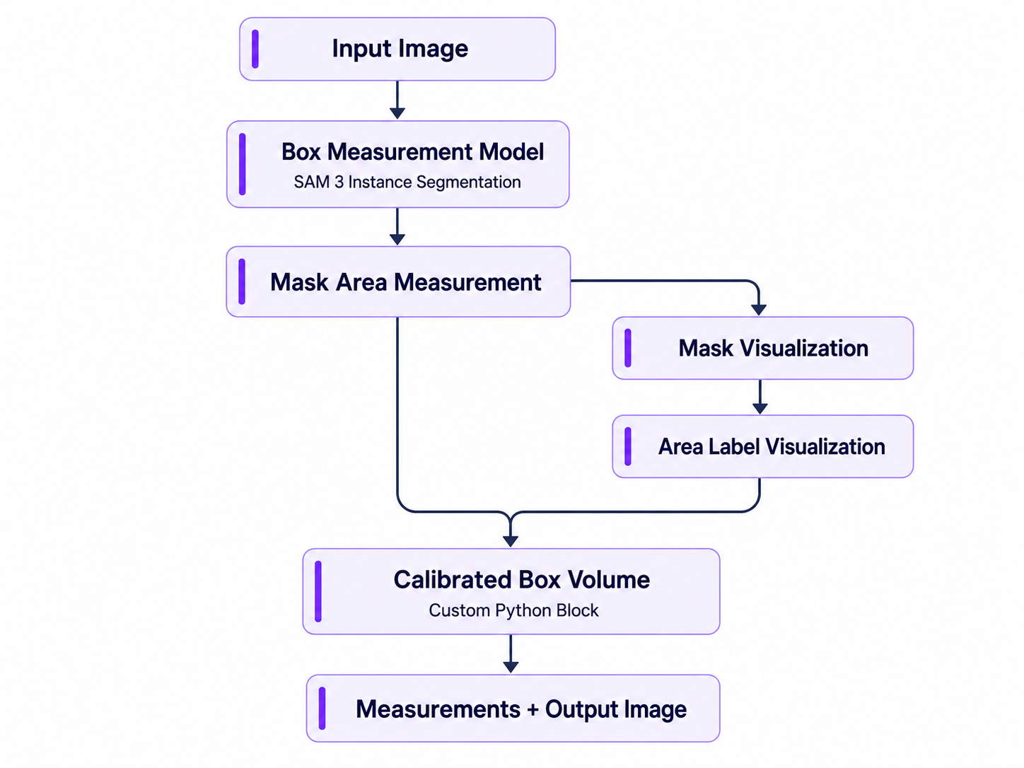
The major components are:
image— Workflow image input.model— Project Model block serving SAM 3.measure_mask_areas— Computes pixel area for every mask.draw_masks— Draws the segmentation masks.draw_area_labels— Displays raw mask-area information.calculate_volume— Performs calibration, physical measurement, volume calculation, and final annotation.- Workflow outputs — Expose the annotated image and structured measurements.
Step 1: Add Box Measurement Model
Add a Project Model block and connect it to the stable endpoint of the Box Measurement Model.
Adding a Project Model block and connecting it to Box Measurement Model endpoint
The Box Measurement Model block runs SAM 3 with the prompts cardboard box and blue paper square.
Box measurement model endpoint
SAM 3 creates a segmentation mask around the box, which provides its pixel dimensions. The Workflow then uses blue-color detection to locate the 5 × 5 cm calibration marker and convert the box measurements from pixels to centimeters. The main output is:
$steps.model.predictions
It includes:
- Class name
- Confidence
- Bounding-box coordinates
- Segmentation-mask geometry
- Detection ID
- Image dimensions
The Workflow references the stable Model endpoint rather than embedding a separate raw SAM 3 block. This means the Model can later be fine-tuned or replaced without changing the rest of the Workflow. So, Box Measurement is the Model asset, while Box Volume Measurement is the Workflow that uses it for calibration and dimension calculations.
cardboard box and blue paper square. SAM 3 requires no initial training and generates a precise mask around the box from a top-down image. The Model is then linked to the Workflow through a Model block, which passes its segmentation predictions to the area-measurement and custom calculation steps. The box mask is used for dimension measurement, while the blue 5 × 5 cm marker is detected more reliably by color in the custom Python block.Step 2: Measure the Segmentation Mask Area
Add the mask area measurement block. This block measures the pixel area of every segmentation mask produced by the Model. It adds area properties to each prediction, including:
area_px— the mask area in pixelsarea_converted— the area after applyingpixels_per_unit
Because pixels_per_unit is set to 1, area_converted is still effectively a pixel-area value. It should not be interpreted as square centimeters. The physical conversion happens later in the custom Python block. That block detects the known 5 × 5 cm calibration marker, calculates the image scale in pixels per centimeter, and uses it to convert the box measurements into centimeters. The custom block reads area_px when available and falls back to counting the non-zero pixels in the segmentation mask when it is not. The custom block must be connected to $steps.measure_mask_areas.predictions so that area_px is present.
Step 3: Visualize the Segmentation
Add Mask Visualization block. This block overlays the segmentation masks on the source image.
{
  "type": "roboflow_core/mask_visualization@v1",
  "name": "draw_masks",
  "image": "$inputs.image",
  "predictions": "$steps.measure_mask_areas.predictions",
  "opacity": 0.45
}
The opacity is set to 0.45, which allows the user to see both:
- The original box.
- The segmentation region used for measurement.
This visualization helps confirm whether SAM 3 has selected the correct box boundary.
Add Area Label Visualization. This block adds mask-area labels to the visualized detections.
{
  "type": "roboflow_core/label_visualization@v2",
  "name": "draw_area_labels",
  "image": "$steps.draw_masks.image",
  "predictions": "$steps.measure_mask_areas.predictions",
  "text": "Area (mask)",
  "text_position": "TOP_LEFT",
  "text_size_mode": "Automatic"
}
The value displayed here is the raw mask area associated with the segmentation result. Final physical measurements in centimeters, square centimeters, and cubic centimeters are calculated by the custom block.
Step 4: Detect the Calibration Marker
From this point, the measurement logic runs inside the Calibrated Box Volume Custom Python block. The block uses the original image to find the blue 5 × 5 cm calibration marker. It converts the image to HSV, isolates blue regions, finds their contours, and selects the largest valid marker.
hsv = cv2.cvtColor(
    calibration_arr,
    cv2.COLOR_BGR2HSV
)

blue = cv2.inRange(
    hsv,
    np.array([85, 45, 35], dtype=np.uint8),
    np.array([140, 255, 255], dtype=np.uint8)
)

contours, _ = cv2.findContours(
    blue,
    cv2.RETR_EXTERNAL,
    cv2.CHAIN_APPROX_SIMPLE
)
After filtering the detected regions, the largest valid contour is used as the calibration marker:
if len(valid) > 0:
    marker_px, marker_contour = max(
        valid,
        key=lambda item: item[0]
    )
The detected marker area is stored in marker_px.
Step 5: Calculate the Image Scale
The calibration marker has a known physical size of 5 × 5 cm, or 25 cm². The Custom Python block uses its detected pixel area to calculate the number of pixels per centimeter:
pixels_per_cm = (
    math.sqrt(marker_px / 25.0)
    if marker_px > 0.0
    else 0.0
)
This pixels_per_cm value is then used to convert box measurements from pixels into centimeters. The block also creates a separate calibration output:
calibration_out = WorkflowImageData.copy_and_replace(
    origin_image_data=raw_image,
    numpy_image=calibration_arr
)
Step 6: Measure the Box Length and Width
The block selects the largest prediction whose class contains box:
box_px, box_index = max(
    box_candidates,
    key=lambda item: item[0]
) if len(box_candidates) > 0 else (0.0, -1)
It then converts the SAM 3 segmentation mask into an OpenCV mask and finds the largest contour:
box_mask = (
    np.asarray(masks[box_index])
    .astype(np.uint8) * 255
)

box_contours, _ = cv2.findContours(
    box_mask,
    cv2.RETR_EXTERNAL,
    cv2.CHAIN_APPROX_SIMPLE
)

largest = max(
    box_contours,
    key=cv2.contourArea
)
A minimum-area rotated rectangle is fitted around the box:
rect = cv2.minAreaRect(largest)
side_a_px, side_b_px = rect[1]
The two sides are converted from pixels to centimeters:
length_cm = float(
    max(side_a_px, side_b_px)
    / pixels_per_cm
)

width_cm = float(
    min(side_a_px, side_b_px)
    / pixels_per_cm
)
Using cv2.minAreaRect() allows the Workflow to measure the box even when it is slightly rotated in the image. If a segmentation mask is unavailable, the code falls back to the prediction bounding box.
Step 7: Calculate the External Box Volume
The box height is configured in the Custom Python block because it cannot be determined from the single top-down image:
height_cm = 5.0The external top area is calculated from the measured length and width:
external_area_cm2 = float(
    length_cm * width_cm
)
The external volume is then calculated using the known height:
external_volume_cm3 = float(
    external_area_cm2 * height_cm
)
The resulting values are available as:
external_top_area_cm2
box_length_cm
box_width_cm
box_height_cm
external_volume_cm3
Step 8: Calculate the Internal Box Volume
The Workflow also estimates the usable internal volume of the box. The wall thickness is configured as:
thickness_cm = 0.2The internal dimensions are calculated by removing the wall thickness from both sides:
internal_length_cm = max(
    0.0,
    length_cm - 2.0 * thickness_cm
)

internal_width_cm = max(
    0.0,
    width_cm - 2.0 * thickness_cm
)

internal_height_cm = max(
    0.0,
    height_cm - 2.0 * thickness_cm
)
The internal base area is then calculated:
internal_area_cm2 = float(
    internal_length_cm
    * internal_width_cm
)
Finally, the internal volume is calculated:
internal_volume_cm3 = float(
    internal_area_cm2
    * internal_height_cm
)
The resulting values are available as:
internal_length_cm
internal_width_cm
internal_height_cm
internal_top_area_cm2
internal_volume_cm3
Step 9: Return the Measurement Results
After the calculations are complete, the block adds the measurements to the output image and creates the final Workflow image:
out = WorkflowImageData.copy_and_replace(
    origin_image_data=image,
    numpy_image=arr
)
The block then returns the measurement image, calibration image, physical measurements, calibration values, and measurement status:
 return {
        'output_image': out,
        'calibration_image': calibration_out,
        'top_area_cm2': float(external_area_cm2),
        'external_top_area_cm2': float(external_area_cm2),
        'box_length_cm': float(length_cm),
        'box_width_cm': float(width_cm),
        'box_height_cm': float(height_cm),
        'wall_thickness_cm': float(thickness_cm),
        'internal_length_cm': float(internal_length_cm),
        'internal_width_cm': float(internal_width_cm),
        'internal_height_cm': float(internal_height_cm),
        'internal_top_area_cm2': float(internal_area_cm2),
        'external_volume_cm3': float(external_volume_cm3),
        'internal_volume_cm3': float(internal_volume_cm3),
        'box_area_px': float(box_px),
        'marker_area_px': float(marker_px),
        'pixels_per_cm': float(pixels_per_cm),
        'measurement_status': status
    }
A successful measurement returns:
successIf the box or calibration marker cannot be found, the block can instead return:
box_not_found
calibration_marker_not_found
box_and_marker_not_found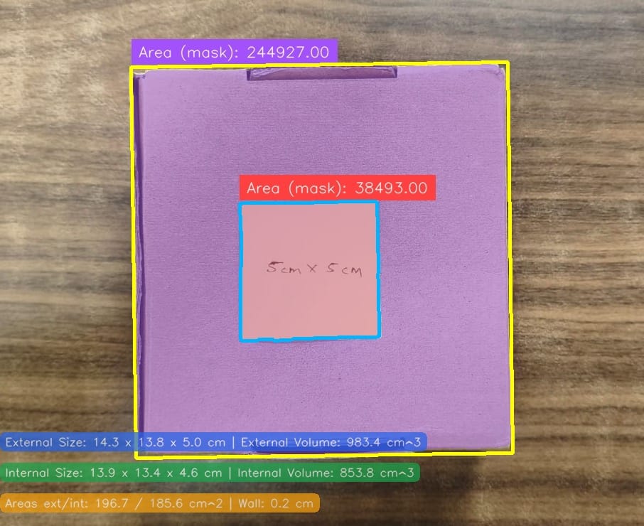
In this Workflow, SAM 3 provides the box segmentation, while the Calibrated Box Volume Custom Python block performs the calibration, dimension conversion, and external and internal volume calculations. The overall output produced by workflow is shown below.
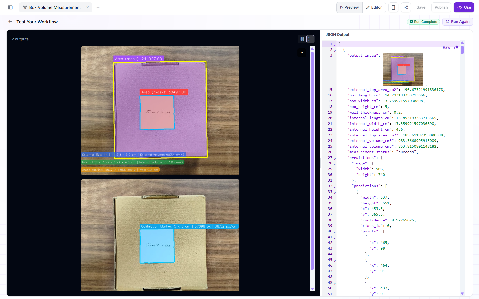
This example workflow uses a static box height, it can be automated further by using Depth Estimation block.
Measurement Assumptions
The Workflow produces the best results when the following conditions are met:
- The camera points directly downward.
- The box top and calibration marker lie on approximately the same plane.
- The entire blue marker is visible.
- The marker measures exactly 5 × 5 cm.
- The marker is not covered by glare, shadows, or other objects.
- Perspective distortion is limited.
- Lens distortion is limited.
- The box is rectangular.
- The external box height is actually 5 cm.
- The wall thickness is approximately 0.2 cm.
- The box is closed, allowing wall thickness to be removed from both the top and bottom.
- The main box is the largest detected box in the image.
- The blue marker appears in every input image.
Small measurement differences may occur between runs because SAM 3 can produce minor variations along the edge of the segmentation mask.
Conclusion
Computer vision can turn images into useful physical measurements such as object dimensions, area, and volume. For simple shapes, this can be done with calibration and geometric formulas, while irregular objects may also need depth information. With Roboflow Workflows, you can combine SAM 3 segmentation, Area Measurement, and Custom Python in one pipeline to build and test a practical volume measurement application. Start with a simple object such as a box, validate the measurements, and then extend the Workflow for more complex use cases.


Cite this Post
Use the following entry to cite this post in your research:
Timothy M. (Aug 24, 2026). How to Measure Volume with Computer Vision. Roboflow Blog: https://blog.roboflow.com/how-to-measure-volume-with-computer-vision/