
We’re living in the era of Industry 4.0, a transformative phase in manufacturing marked by the integration of smart technologies like IoT, AI, robotics, and advanced data analytics. At the heart of this revolution is machine vision, enabling machines to "see" and make intelligent decisions in real time. From monitoring production lines and ensuring product quality to detecting microscopic defects, machine vision is now a cornerstone of the modern, data-driven factory.
In this blog, we will show you how to train a custom object detection model using Roboflow auto-training feature. Using an electronic manufacturing use case as an example (e.g. detecting packages, identifying electronic components) you'll learn how to:
- Prepare and annotate your dataset
- Train your model in Roboflow
- Test and deploy your model for real-world applications
Whether you are improving quality control or implementing smarter automation, this guide will help you create a vision solution that fits your factory's needs.
What Is Machine Vision?
Machine vision encompasses the technologies and methodologies that enable automated systems, particularly in industrial and manufacturing domains, to acquire, process, and analyze visual information from their environment. As a subset of computer vision, machine vision is specifically engineered for structured, high-speed, and high-precision tasks within controlled environments such as production lines.
A typical machine vision system integrates imaging hardware, such as industrial cameras and optics, with advanced software algorithms to perform real-time analysis. Captured images are processed to extract critical features such as dimensional measurements, part identification, alignment verification, and defect detection. Based on the extracted data, the system can initiate decision-making processes or trigger automated responses, enabling fully autonomous operation without human intervention.
Machine Vision System Architecture in Manufacturing
The following diagram illustrates a machine vision system architecture in a manufacturing environment using Roboflow, which enables AI-powered visual inspection and analysis. Here's a detailed breakdown of each component and its role:

Cameras (Input Devices)
The camera captures real-time visual data from the manufacturing floor. It could be fixed industrial cameras, webcams, IP/RTSP cameras, drone cams, etc. The cameras are connected via RTSP / USB / GigE protocols. Cameras are the eyes of the system, continuously feeding visual input (images or video) for inspection, monitoring, and analysis.
Roboflow (Machine Vision AI Platform)
The trained and deployed computer vision model acts as the AI brain that processes the visual data from the cameras. The Roboflow inference server runs custom-trained computer vision models (e.g., for defect detection, part counting, or classification). It outputs meaningful results such as "pass/fail," "label OK," "defect detected," etc. The results are sent to the PLC and HMI using standard industrial protocols like MQTT or OPC-UA.
PLC (Programmable Logic Controller)
PLC is the central controller for managing industrial automation processes. PLC receives decision signals from Roboflow and triggers actions on devices based on AI insights, e.g. rejecting a defective part or allowing a good product to move forward.
Devices (Actuators or Machines)
These devices are the conveyor or other machine like robotic arms that process the commands to take actions (e.g. pick and place selected items or sort them). The devices may either help in proceeding with approved items or remove or flag defective items. These devices act based on decisions made by the PLC, which were influenced by Roboflow’s AI vision results.
HMI (Human-Machine Interface)
This is the visual dashboard for operators which displays AI inspection results, shows alerts, logs, or real-time footage. It can also allow manual override or system monitoring. HMI gets data from Roboflow via MQTT / OPC-UA. These are common protocols in IIoT (Industrial IoT) and SCADA systems.
Let’s understand how this overall system works:
- Cameras capture images/videos of products or machinery in real-time.
- Roboflow processes this data using vision models (e.g., for defect detection, counting, inspection).
- AI decisions are sent to PLC and HMI: The PLC, which then commands devices to take appropriate action; the HMI, for display and user interaction.
- Devices either continue, reject, or flag items based on inspection results.
- Operators view everything through the HMI in real time.
Machine Vision Applications in Manufacturing
Below is a detailed exploration of machine vision applications in manufacturing categorized by functional areas.
Procurement
Raw Material Inspection: Ensuring the quality of raw materials is foundational to manufacturing excellence. Machine vision systems automate the inspection process by capturing high-resolution images of incoming materials and analyzing them for defects such as surface imperfections or dimensional inaccuracies. This automation helps early detection of substandard materials and prevent production issues downstream while maintaining product integrity.

Component Sorting: Efficient assembly processes rely on accurate sorting of components. Machine vision technology enables automated systems to identify and categorize parts based on attributes like size, shape, and color. This precision reduces manual labor, accelerates production lines, and minimizes errors associated with incorrect component usage.

Automation
Robot Guidance: Integrating machine vision with robotics enhances the flexibility and accuracy of automated tasks. Vision-guided robots can locate parts, determine their orientation, and perform complex assembly operations without the need for precise manual positioning. This capability allows for quick adaptation to different products and reduces reliance on fixed tooling.

Part Counting: Automated part counting systems equipped with machine vision swiftly and accurately tally components during manufacturing and packaging. By analyzing visual data, these systems ensure correct quantities are used or packaged, enhancing inventory accuracy and reducing the risk of shortages or overages.

Quality
Defect Detection: Maintaining high product quality necessitates the identification of defects during production. Machine vision systems assist in detecting a wide range of product defects, from surface imperfections to complex anomalies and irregularities. Through real-time analysis of visual data, these systems pinpoint defects that may be missed by conventional methods. Machine vision system ensures only products meeting quality standards proceed to market.

Specification Accuracy: Ensuring products adhere to design specifications is critical for functionality and compliance. Machine vision systems verify dimensions, shapes, and other critical parameters against predefined standards. This verification process guarantees that each product aligns with its intended design, reducing the likelihood of malfunctions or customer dissatisfaction.

Safety
Protective Gear Check: Worker safety is paramount in industrial environments. Machine vision systems monitor and verify the use of personal protective equipment (PPE) by analyzing visual data to ensure compliance with safety protocols. For example, these systems can detect whether employees are wearing hard hats, safety glasses, gloves, and other required gear, alerting supervisors to any non-compliance in real-time.
Access Control: Securing restricted areas within a facility is vital for both safety and confidentiality. Machine vision-based access control systems identify individuals and determine their authorization status, permitting or denying entry accordingly. This technology enhances security by preventing unauthorized access and can integrate with existing security infrastructure for comprehensive monitoring.

Maintenance
Monitor Wear and Tear: Proactive maintenance is essential to prevent equipment failures. Machine vision systems continuously monitor machinery for signs of wear and tear, such as surface degradation or component misalignment. By detecting these issues early, maintenance can be scheduled before failures occur, reducing downtime and extending equipment lifespan.
Detect Unusual Patterns: Identifying anomalies in equipment behavior can preempt serious malfunctions. Machine vision systems analyze operational data to detect patterns that deviate from normal performance, such as A factory’s robotic arms occasionally fail mid-operation due to causing slippage or mis-picks, showing irregular movements. Early detection enables timely intervention, preventing costly repairs and ensuring continuous operation.

Inventory
Barcode Scanning: Efficient inventory management relies on accurate tracking of products. Barcode scanning using machine vision helps in automating the identification and logging of items as they move through the supply chain. This automation reduces human error, speeds up processing times, and provides real-time inventory visibility.

Storage Optimization: Maximizing warehouse space and ensuring easy retrieval of items are critical for operational efficiency. Machine vision systems analyze storage layouts and item dimensions to recommend optimal placement strategies. This optimization enhances space utilization and reduces retrieval times thus supporting in effective inventory management.
Logistics
Package Inspection: Ensuring packages are correctly sealed, labeled, and undamaged before shipment is important for customer satisfaction. Machine vision systems automate the inspection process by analyzing visual data to verify package integrity and labeling accuracy. This reduces the risk of shipping errors and returns.

Pallet Tracking: Accurate tracking of pallets within warehouses and during transit ensures efficient supply chain operations. Machine vision systems identify and monitor pallets, providing real-time location data and ensuring they are routed correctly. Pallet tracking enhances overall logistical efficiency.

There are various machine vision applications that can be integrated into manufacturing industries to achieve significant improvements in productivity, quality, and safety which leads to a more streamlined and competitive operation.
Building Machine Vision Application using Roboflow
In this section, we will explore how to build machine vision applications for manufacturing use cases. As previously discussed, machine vision serves a wide range of applications within the manufacturing sector. Here, we will focus on two specific implementations i.e. package detection and identification, and PCB component detection for the electronics manufacturing industry. To achieve this, we will train two distinct object detection models using Roboflow, each designed for its respective task. These models will then be integrated into a unified application using Roboflow Workflows. Let’s follow the steps for building the application.
Step #1: Build Computer Vision Models
Create an object detection project in Roboflow and collect and upload the images. I have uploaded the following images of packages of hardware development kits for the first model package detection and identification.

After uploading the images, label images using Roboflow annotate.

Similarly for second PCB component detection model, I have collected image of different hardware kits and circuit boards.

Uploaded the images and annotated each images for the different components on each hardware with class labels such as Button, Capacitor, Clock, Connector, Diode, Electrolytic Capacitor, IC, Inductor, Led, Pins, Resistor, Switch, Transistor etc.

After labeling all images the dataset was created and model was trained using Roboflow auto-train. So, we have built the two models package detection and identification and PCB component detection. The package detection and identification model will be utilized to automatically detect and classify packages moving along conveyor belts, enabling efficient sorting for packaging and distribution processes. In parallel, the PCB component detection model will be deployed for quality assurance, ensuring that printed circuit boards (PCBs) contain all necessary components, such as the correct number of integrated circuits (ICs) and other critical hardware elements, before proceeding to the next stage of manufacturing.
Step #2: Build Roboflow Workflow
In this step we will build Roboflow Workflow that uses both the object detection models that we trained in step #1. We will build two Workflows, first workflow will detect and count electronic board package while the other detects and verify that the required number of components are available on the manufactured PCB. We will learn how to build two Workflows for the same.
Workflow #1: Detect and count electronic package on conveyor belt
In this example, we will create a workflow that uses a package detection and identification model to detect, identify, and count packages as they move along a conveyor belt. The counting is based on the logic of detecting objects crossing a predefined line using computer vision. The overall workflow is illustrated below.

The output block of this workflow should be configured as following because we will be using the output variables in our code.

Now, deploy the Workflow using code below.
# Import the InferencePipeline object
from inference import InferencePipeline
import cv2

previous_count_out = 0
class_total_counts = {}

# Mapping of actual class name and display label
class_label_map = {
    "jetson_nano_2gb": "Jetson Nano",
    "opla_iot": "Opla IoT",
    "reterminal": "reTerminal"
}

# Initialize all counts to 0
for class_name in class_label_map:
    class_total_counts[class_name] = 0

def my_sink(result, video_frame):
    global previous_count_out, class_total_counts

    visualization = result["label_visualization"].numpy_image
    tracked = result["byte_tracker_output"]["tracked_detections"]
    class_names = tracked.data.get("class_name", [])

    # line_counter_output logic
    current_count_out = result.get("line_counter_output", 0)
    if current_count_out > previous_count_out:
        for cls in class_names:
            cls_str = str(cls)
            if cls_str in class_total_counts:
                class_total_counts[cls_str] += 1
        previous_count_out = current_count_out

    # Draw text for all defined classes
    y = 30
    for cls_name, display_label in class_label_map.items():
        count = class_total_counts.get(cls_name, 0)
        text = f"{display_label}: {count}"

        (w, h), _ = cv2.getTextSize(text, cv2.FONT_HERSHEY_SIMPLEX, 0.6, 1)
        cv2.rectangle(visualization, (10, y - h), (10 + w + 10, y + 10), (255, 255, 255), -1)
        cv2.putText(visualization, text, (15, y + 5), cv2.FONT_HERSHEY_SIMPLEX, 0.6, (0, 0, 0), 1)
        y += 30

    # Show frame
    cv2.imshow("Counting Packages", visualization)
    cv2.waitKey(1)

# initialize a pipeline object
pipeline = InferencePipeline.init_with_workflow(
   api_key="ROBOFLOW_API_KEY",
    workspace_name="tim-4ijf0",
    workflow_id="package-counting",
    video_reference="VID20250421143905.mp4",  # Path to video, device id (int, usually 0 for built in webcams), or RTSP stream url
    max_fps=30,
    on_prediction=my_sink
)
pipeline.start()  # start the pipeline
pipeline.join()  # wait for the pipeline thread to finish
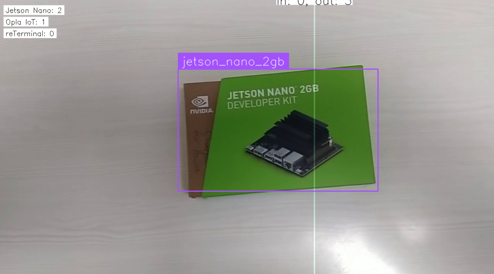
The above code runs a computer vision workflow to detect, identify, and count packages (like Jetson Nano, Opla IoT, reTerminal) as they move through a conveyor belt. It processes a video stream of packages moving on a conveyor belt, detects specific types of packages (i.e. class), and keeps a count of how many of each type have passed a crossing line in the frame. The system updates and displays the class wise counts on the screen, showing the name and quantity of each detected package type. You should see output similar to following.


Workflow #2: Detect and verify number of PCB components
In this example, we will create a Roboflow Workflow that detects various components on a PCB and displays the count for each detected component. This workflow is useful for verifying whether a manufactured PCB contains all the required components, helping ensure quality and completeness in the production process. Create a Workflow as following.

In this workflow, we will utilize a Custom Python Block, which enables the execution of user-defined Python code. We’ll use this block to calculate the count of each component type detected by the model. This approach helps in verifying whether the PCB includes the correct number of required components, ensuring accuracy in the inspection process. In this Workflow we will first add the Object Detection Model block and configure it with the PCB component detection model that we trained earlier. You can also use bounding box visualization. Then add add custom Python block in your Workflow and use the following code.
def run(self, detections) -> BlockResult:
    # Initialize a dictionary to store class-wise counts
    class_counts = {}

    # Convert the detections to a regular list if it's in array format
    class_names_list = detections.data.get("class_name", [])
    class_names_list = class_names_list.tolist() if isinstance(class_names_list, np.ndarray) else class_names_list

    # Count each class
    for class_name in class_names_list:
        if class_name in class_counts:
            class_counts[class_name] += 1
        else:
            class_counts[class_name] = 1

    # Print the class-wise counts
    print("Class-wise counts:", class_counts)

    # Return the result
    return {"result": class_counts}
Your custom Python block should look like following.

The Custom Python Block is required to process the model’s prediction results and compute a class-wise count of detected components on a PCB. This block:
- Accept model predictions from the previous block in the workflow (object detection results).
- Extract class labels of all detected components.
- Compute and maintain a count of each component type (e.g., resistors, capacitors, ICs).
- Format the output in structured format that clearly shows the count per class.
inference server start command to initiate the server, which will run in a Docker container and be accessible at http://localhost:9001.Finally configure the output block to display results as shown in image below.

When you run the workflow and upload below image of PCB,

you should see that the custom Python block returns the component count as below.
{
    "component_count": {
      "IC": 7,
      "Connector": 12,
      "Clock": 2,
      "Button": 1,
      "Electrolytic Capacitor": 2,
      "Led": 4,
      "Diode": 2,
      "Capacitor": 10
    }
This information can be used for further analysis.
Use Machine Vision in Manufacturing
We've explored how machine vision is revolutionizing modern manufacturing through intelligent automation and quality control. The machine vision systems integrate cameras, AI models, and industrial devices like PLCs and HMIs to automate visual inspection tasks. We covered two real-life examples:
- Detecting packages on a conveyor belt.
- Checking PCB components in electronics manufacturing.
Using Roboflow, we trained AI models, set up workflows, and added custom logic (with Python) to count and verify parts. These examples show how easy it is to build powerful machine vision and robust machine vision applications using Roboflow. Applications like this helps factories to improve quality, save time, and cut down on manual work.
Ready to bring computer vision to your factory floor? With Roboflow’s auto-training feature, it’s never been easier to go from annotated images to a production-ready object detection model. Start building smarter automation, improve quality control, and deploy AI that works for your specific manufacturing needs - all in one platform. Talk to an AI expert to discuss your unique manufacturing use cases.
We’re SOC 2 Type II compliant, support custom security rules, and power customers operating at global scale with terabytes of data today.
Cite this Post
Use the following entry to cite this post in your research:
Timothy M. (Apr 22, 2025). Machine Vision in Manufacturing. Roboflow Blog: https://blog.roboflow.com/machine-vision-in-manufacturing/