
A computer vision system can detect appliance state (lights on or off, fan spinning or stopped) using a single camera, replacing multiple dedicated sensors with one flexible node. This tutorial builds the full stack: a Python inference script using a Roboflow-trained object detection model publishes appliance status to an MQTT broker, a JavaScript web app reads that status and lets users issue remote commands, and ESP32 firmware executes those commands to physically toggle a light and fan. The dataset and all project code are available on Roboflow Universe and GitHub.
Ever left home only to wonder if you turned off the lights or left the fan running? It happens to most of us! In this blog post, we will learn to build a smart solution to keep an eye on things like whether the lights are still on at home using computer vision.
Imagine having a camera set up in your home that can see if the lights are on or off and whether the fan is spinning or not. With this system, you can check in on your home from anywhere using your phone or computer, and even control your appliances remotely. It's like having a personal home monitor that helps you save energy and worry less about forgetting stuff.
There are many dedicated sensors available which can be used to build such system. But, you can also use computer vision with a camera as a sensor. The benefits of this are:
- Instead of installing multiple sensors for each appliance, a single camera does the job, saving money on hardware and installation.
- Computer vision can detect various appliances without needing specific sensors for each, making it flexible for different needs.
- No need for complex wiring or setup for each appliance; just position the camera strategically, and you're good to go.
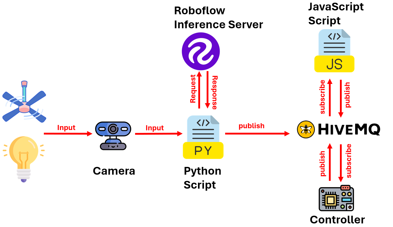
Smart Home Monitoring with Computer Vision: How the System Works
The smart home monitoring and control system we will build in this guide consists of three main components working together to monitor and control home appliances such as lights and fans.
Camera Node:
- A camera node runs a Python script that continuously monitors the home environment.
- The script communicates with a computer vision model, which is built and deployed using Roboflow.
- The object detection model is trained to detect the on/off status of lights and the spinning/not spinning status of fans.
- The detected status of the appliances is published to an MQTT broker.
JavaScript Web Application:
- A JavaScript application receives the status updates from the MQTT broker.
- The application updates the UI based on the received status, showing whether the light is on or off and whether the fan is spinning or not.
- The UI allows the user to manually control the appliances. For instance, if the light is detected as on, the user can use the UI to turn it off.
IoT Device (Controller):
- When the user interacts with the UI to turn off an appliance, the command is published to the MQTT broker on a specific topic.
- An IoT device, which is connected to the appliances, subscribes to this topic to receive commands from the JavaScript application.
- Upon receiving the command, the IoT device performs the necessary action to turn off the light or fan.
The following figure shows the working of the system.
How to Build a Smart Home Monitoring System with Computer Vision
The following steps were taken to build the system.
- Collect and label the dataset
- Train object detection model
- Write inference script to detect status and send it over MQTT
- Build JavaScript App to monitor and control home environment
- Build firmware to perform control operation
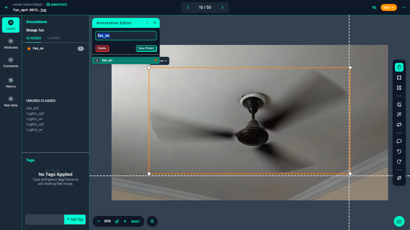
Step #1: Collect and label the dataset
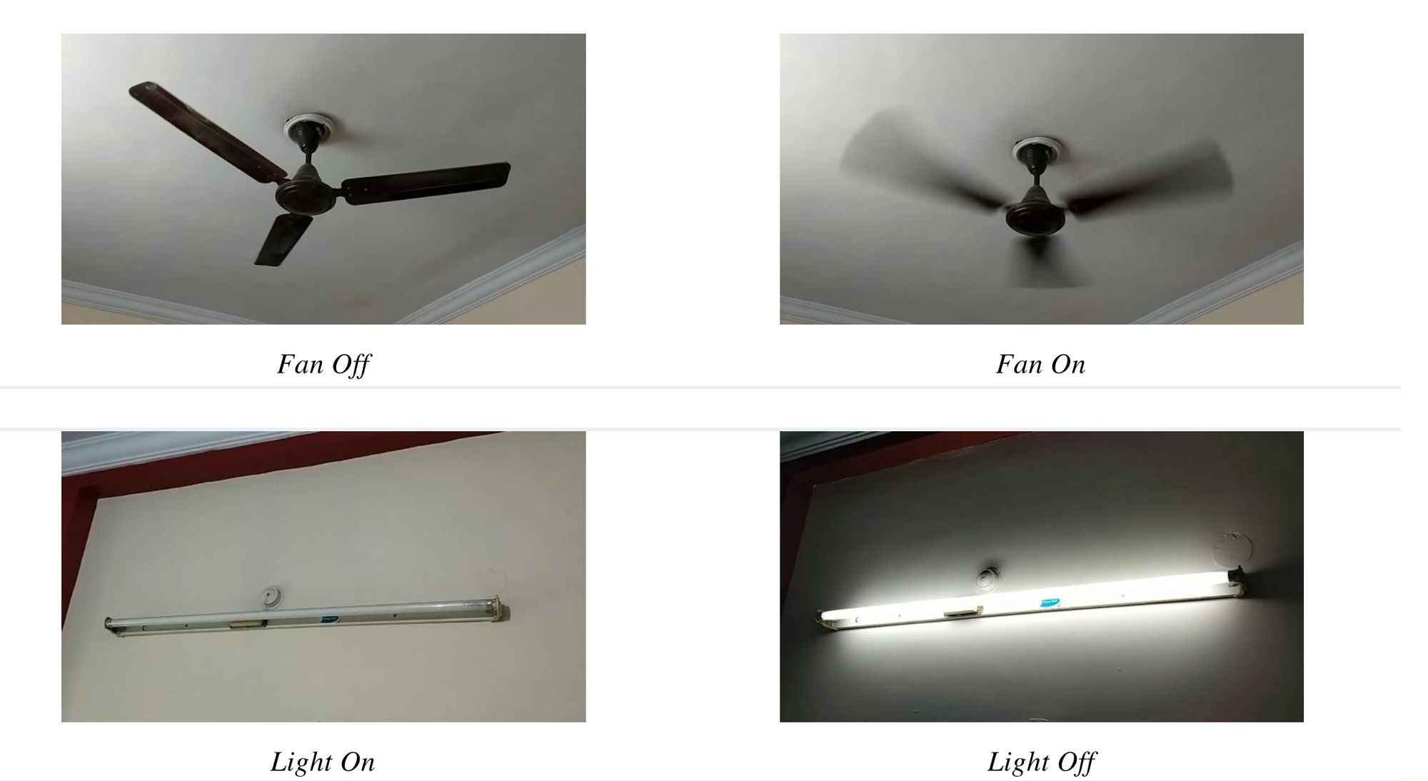
The dataset of various home appliances, such as lights and fans, has been collected. This dataset includes images of the appliances in their different states, such as light on and off, and fan on and off. After collecting the dataset, it was uploaded to Roboflow for labeling. Using bounding boxes, the appliances in the images were labeled to create an object detection project.
Step #2: Train object detection model
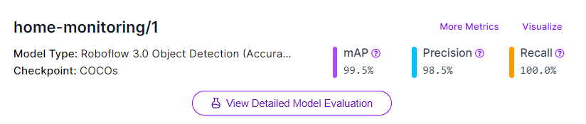
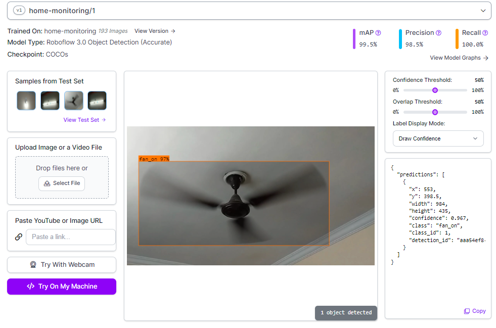
After completing the labeling process, a version of the dataset is generated, and the model is trained using the Roboflow auto-training option. The training accuracy achieved is 99.5%.
Upon completing the training, the model is automatically deployed to a cloud API. Roboflow offers multiple options for testing and deploying the model, including live testing in a web browser and deployment to edge devices. The image below shows the model being tested through Roboflow’s web interface.
Step #3: Write inference script to detect status and send it over MQTT
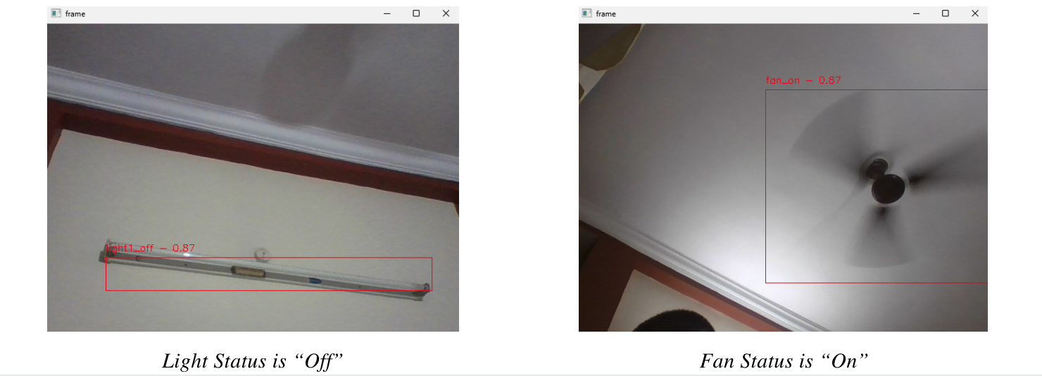
Now we will write the inference script in python to detect Light and Fan based on our trained model. The code uses OpenCV library to capture real-time video footage from camera and a pre-trained object detection model from Roboflow to identify the on/off status of lights and the spinning status of fans. The object detection model processes each video frame to detect the specified objects. When a light or fan is detected, the code publishes the status to an MQTT broker, to the topics "home/light" and "home/fan" based on the detected object's class name which actually indicate the status of the object i.e. “light1_on”, “light1_off”, “fan_on” and “fan_off”.
import cv2
import time
import paho.mqtt.client as mqtt
from inference_sdk import InferenceHTTPClient

broker_address = "broker.hivemq.com"
port = 1883

client = mqtt.Client(client_id="smart_home_1")
client.connect(broker_address, port)

# Initialize InferenceHTTPClient
CLIENT = InferenceHTTPClient(
    api_url="https://detect.roboflow.com",
    api_key="ROBOFLOW_API_KEY"
)

video = cv2.VideoCapture(0)

while True:
    ret, frame = video.read()
    if not ret:
        break

    # Infer on the frame
    result = CLIENT.infer(frame, model_id="home-monitoring/1")
    detections = result['predictions']

    for bounding_box in detections:
        x0 = int(bounding_box['x'] - bounding_box['width'] / 2)
        x1 = int(bounding_box['x'] + bounding_box['width'] / 2)
        y0 = int(bounding_box['y'] - bounding_box['height'] / 2)
        y1 = int(bounding_box['y'] + bounding_box['height'] / 2)
        class_name = bounding_box['class']
        confidence = bounding_box['confidence']

        # Publish detected class to appropriate MQTT topic
        if class_name in ["light1_on", "light1_off"]:
            client.publish("home/light", class_name)
        elif class_name in ["fan_on", "fan_off"]:
            client.publish("home/fan", class_name)

        cv2.rectangle(frame, (x0, y0), (x1, y1), color=(0, 0, 255), thickness=1)
        cv2.putText(frame, f"{class_name} - {confidence:.2f}", (x0, y0 - 10), cv2.FONT_HERSHEY_SIMPLEX, 0.5,
                    (0, 0, 255), 1)

    cv2.imshow('frame', frame)

    if cv2.waitKey(1) & 0xFF == ord('q'):
        break

video.release()
cv2.destroyAllWindows()
The output similar to following will be generated when you run the code. Here we see light and fan in individual frames with their status.
Step #4: Build JavaScript App to monitor and control home environment
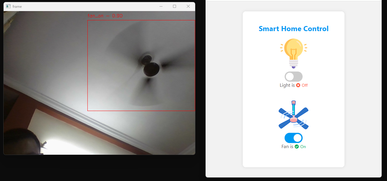
In this step, we will build a JavaScript-based application that provides a user interface (UI) to display the status of the light and fan based on MQTT messages published by the Python inference script. The JavaScript uses the MQTT library to subscribe to and publish messages to and from the MQTT topics. This app also allows users to control home appliances, such as the light and fan in our example. Following is the output of the JavaScript App
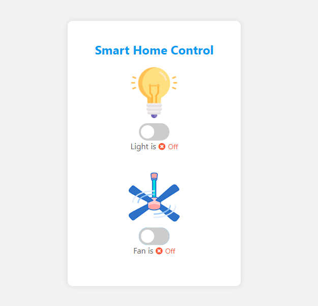
This JavaScript code creates a user interface (UI) for smart home control. The UI displays the status of the light and fan based on MQTT messages received from a broker. It subscribes to MQTT topics for "home/light" and "home/fan". When a message is received, the code updates the UI accordingly, toggling the status of the light or fan switch. Additionally, users can manually control the appliances using toggle switches provided in the UI.
When a user toggles the switch, the code sends a corresponding MQTT message to the broker, indicating the desired state of the appliance. To prevent rapid toggling and ensure smooth operation, the code implements a pause mechanism that temporarily disables processing of MQTT messages after a switch is toggled, effectively pausing for a short duration before allowing further toggles.
Step #5: Build firmware to perform control operation
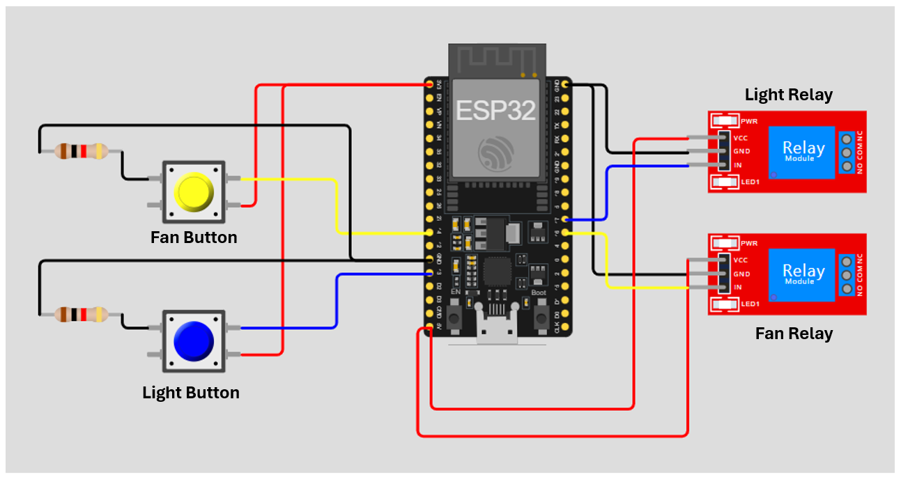
Finally, in this section we will build our firmware which actually perform the home appliances control. The following hardware components are required to build the device.
- ESP32 Development Kit x1
- 1-Channel Relay module x2
- Resistor (1 KΩ) x2
- Push Buttons x2
- Jumper Wires
The firmware is designed to control a light and a fan using an ESP32 microcontroller. It connects to a Wi-Fi network and subscribes to MQTT topics to receive commands for controlling the light and fan. The system also allows manual control via physical push buttons connected to the ESP32.
Upon initialization, the microcontroller connects to a specified Wi-Fi network and sets up an MQTT client to communicate with an MQTT broker. The firmware subscribes to specific MQTT topics, "home/light" and "home/fan", to receive commands for turning the light and fan on or off. It receives these command from the JavaScript App that we built in previous section. The messages are received when user clicks the buttons on the UI of JavaScript App. When a message is received on these topics, the callback function processes the message and updates the state of the respective relay, thereby controlling the appliances.
The firmware also allows for manual control via physical push buttons connected to the ESP32. The state of each button is continuously read in the main loop, and pressing a button toggles the state of the corresponding relay to turn the light or fan on or off. This state change is reflected immediately without sending any MQTT messages, ensuring that the manual control operates independently of the remote control functionality. The firmware also ensures that the MQTT client remains connected, continually processing any incoming messages. This setup provides a flexible control system for home appliances, combining remote control via MQTT with local manual control. The following circuit diagram show how to build the device.
Here’s the firmware code in C:
#include <WiFi.h>
#include "PubSubClient.h"

// Button and relay pins
const int BTN1 = 13;
const int BTN2 = 14;
const int relay1 = 17;
const int relay2 = 16;

// Button states
bool lastBTN1_State = LOW;
bool lastBTN2_State = LOW;

// Relay states
bool relay1State = LOW;
bool relay2State = LOW;

// WiFi and MQTT settings
const char* ssid = "YOUR_WIFI_SSID";
const char* password = "YOUR_WIFI_PASSWORD";
const char* mqttServer = "broker.hivemq.com";
const int port = 1883;

WiFiClient espClient;
PubSubClient client(espClient);

void setup() {
  Serial.begin(115200);
  pinMode(BTN1, INPUT);
  pinMode(BTN2, INPUT);
  pinMode(relay1, OUTPUT);
  pinMode(relay2, OUTPUT);

  Serial.print("Connecting to ");
  Serial.println(ssid);

  wifiConnect();

  Serial.println("\nWiFi connected");
  Serial.println("IP address: ");
  Serial.println(WiFi.localIP());
  Serial.println(WiFi.macAddress());

  client.setServer(mqttServer, port);
  client.setCallback(callback);
}

void wifiConnect() {
  WiFi.mode(WIFI_STA);
  WiFi.begin(ssid, password);
  while (WiFi.status() != WL_CONNECTED) {
    delay(500);
    Serial.print(".");
  }
}

void mqttReconnect() {
  while (!client.connected()) {
    Serial.print("Attempting MQTT connection...");
    String clientId = "ESP32Client-" + String(random(0xffff), HEX);
    if (client.connect(clientId.c_str())) {
      Serial.println(" connected");
      client.subscribe("home/light");
      client.subscribe("home/fan");
    } else {
      Serial.print("failed, rc=");
      Serial.print(client.state());
      Serial.println(" try again in 5 seconds");
      delay(5000);
    }
  }
}

void callback(char* topic, byte* message, unsigned int length) {
  Serial.print("Message arrived on topic: ");
  Serial.print(topic);
  Serial.print(". Message: ");
  String stMessage;

  for (int i = 0; i < length; i++) {
    Serial.print((char)message[i]);
    stMessage += (char)message[i];
  }
  Serial.println();

  if (String(topic) == "home/light") {
    if (stMessage == "light1_on") {
      relay1State = HIGH;
    } else if (stMessage == "light1_off") {
      relay1State = LOW;
    }
    digitalWrite(relay1, relay1State);
  }

  if (String(topic) == "home/fan") {
    if (stMessage == "fan_on") {
      relay2State = HIGH;
    } else if (stMessage == "fan_off") {
      relay2State = LOW;
    }
    digitalWrite(relay2, relay2State);
  }
}

void loop() {
  // Read the current state of the buttons
  bool currentBTN1_State = digitalRead(BTN1);
  bool currentBTN2_State = digitalRead(BTN2);

  // Check if button 1 state has changed
  if (currentBTN1_State != lastBTN1_State) {
    lastBTN1_State = currentBTN1_State;
    if (currentBTN1_State == HIGH) {
      relay1State = !relay1State;
      digitalWrite(relay1, relay1State);
      Serial.println("Button 1 Clicked - Light toggled");
    }
  }

  // Check if button 2 state has changed
  if (currentBTN2_State != lastBTN2_State) {
    lastBTN2_State = currentBTN2_State;
    if (currentBTN2_State == HIGH) {
      relay2State = !relay2State;
      digitalWrite(relay2, relay2State);
      Serial.println("Button 2 Clicked - Fan toggled");
    }
  }

  if (!client.connected()) {
    mqttReconnect();
  }
  client.loop();
}
This firmware allows both remote control (via MQTT messages from JavaScript application) and manual control (via hardware push buttons) for a light and a fan, making it a versatile solution for smart home automation.
Smart Home Monitoring with Vision AI
Today we have built an integrated smart home control system comprising three main components: an object detection inference script, a JavaScript application, and a firmware for the ESP32 microcontroller.
The object detection script runs on a camera-based node, detecting the on/off status of a light and a fan, and publishing these statuses to an MQTT broker. The JavaScript application subscribes to these MQTT topics, updating the UI to display the current status of the appliances and allowing users to control them.
The ESP32 firmware subscribes to the same MQTT topics, receiving commands from the JavaScript application to toggle the light and fan, while also allowing manual control via physical buttons. This system enables seamless integration of computer vision and Internet of Things, enhancing the convenience and functionality of home automation.
Ready to power your own smart home projects with vision? Get started free.
All code for this project is available at GitHub. The dataset used for this project is available on Roboflow Universe.
Cite this Post
Use the following entry to cite this post in your research:
Timothy M. (Jun 5, 2024). Smart Home Monitoring with Computer Vision and IoT. Roboflow Blog: https://blog.roboflow.com/smart-home-monitoring/