

Computer vision reliably identifies wood surface defects, including dead knots, cracks, and resin pockets, enabling automated sorting before defective material reaches production. You can train a wood defect detection model that spots cracks, holes, and three kinds of knots with RF-DETR and Roboflow.
Before a piece of wood can be used in furniture, construction, flooring, or other products, it often needs to be inspected for defects. Cracks, holes, and knots can affect both the appearance and quality of the final product, making inspection an important part of the manufacturing process.
Computer vision can help automate this process. By training an object detection model to recognize different types of defects, manufacturers can use cameras to inspect wood surfaces and identify potential issues automatically.
In this tutorial, we will build a wood defect detection system using Roboflow. We will use a dataset containing five classes of wood defects, including cracks, holes, and different types of knots, to train an object detection model. We will then test the model to see how it can automatically identify and locate defects in new images.
By the end of this tutorial, you will have a working system that demonstrates how computer vision can be used to support automated wood inspection and quality control.
What Are Wood Defects?
Wood defects are irregularities or imperfections that can affect the appearance, quality, or structural properties of a piece of wood. These defects can occur naturally as the tree grows or develop later during processing, drying, handling, or manufacturing.
Some defects are primarily cosmetic, while others can affect the strength or usability of the wood. Common examples include cracks, holes, and knots. Knots form around the areas where branches were connected to the tree and can vary in appearance and condition. A knot may be firmly connected to the surrounding wood, known as a live knot, or loose and separated from the surrounding wood, known as a dead knot. In some cases, cracks can also develop around or through a knot.
In this project, we will focus on five types of wood defects:
- Crack: A visible split or separation in the wood.
- Dead knot: A knot from a branch that had already died before the tree was cut. It isn't fused to the wood around it, so it's loose and can sometimes fall out.
- Holes: Openings or missing areas in the wood surface.
- Knot with crack: A knot that contains or is associated with a visible crack.
- Live knot: A knot from a branch that was still alive and growing when the tree was cut. It's fused to the wood around it, so it stays firmly in place.
Identifying these defects is an important part of wood inspection because their presence, type, and location can help determine the quality of a piece of wood. In the next sections, we will train a computer vision model that can automatically identify and locate these defects in images.
Building a Wood Defect Detection System
For this tutorial, we will use computer vision to automate the inspection of wood for common surface defects. We will start with a public dataset from Roboflow Universe, prepare it for training, and fine-tune a custom RF-DETR object detection model. Once the model is trained, we will connect it to a Roboflow Workflow that can process images and visualize the detected defects.
The final Workflow will identify defects on the wood surface, show where each defect was found, label the type of defect, and keep track of the total number of detections.
Step 1: Log in to Roboflow
Start by signing in to your Roboflow account. If you do not already have an account, you can create one for free.

Step 2: Fork the Wood Defect Dataset
Collecting and annotating enough images of wood defects from scratch can take considerable time, so we will start with an existing dataset from Roboflow Universe.
The New Defects in Wood dataset contains 1,269 images with annotations for five defect classes:
- Crack
- Dead knot
- Holes
- Knot with crack
- Live knot
These classes give the model several different types of defects to learn, including both cracks and different forms of knots that can have similar visual characteristics.
Note: Since this project is intended as a demonstration, we will work with a limited set of defect classes to keep the example focused. For a production system, you would likely want to cover a wider range of defects that are relevant to your specific inspection process. You could start with a larger dataset or use Roboflow to upload and annotate your own images, allowing you to add additional defect classes and examples from the environment where the model will eventually be deployed.
To use the dataset in your own workspace, open it in Roboflow Universe and click Fork Dataset in the top-left corner. Choose your workspace as the destination and click Fork Dataset again.
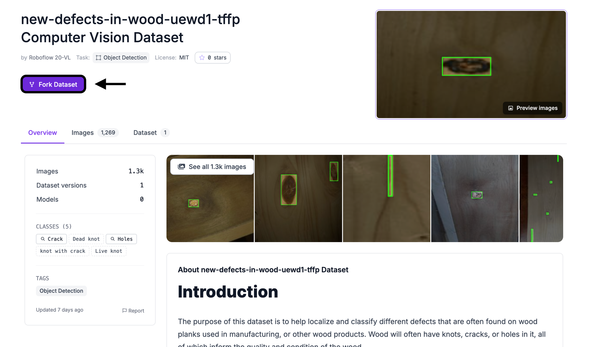
Roboflow will create a copy of the dataset in your workspace. From this copy, you can generate your own dataset version and configure its preprocessing and augmentation settings without modifying the original dataset.
Step 3: Train an RF-DETR Model
With the dataset in your workspace, open the project and select Train. Choose Custom Training as the training engine.
When selecting the model architecture, choose RF-DETR and use the Small model size. RF-DETR is designed for real-time object detection and can be fine-tuned on custom datasets, making it a good fit for this type of visual inspection task.
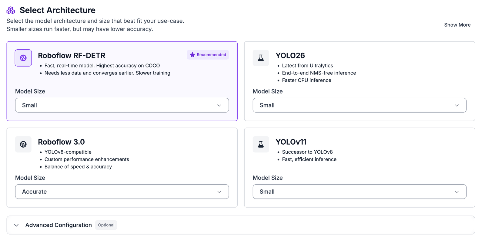
The model will learn to locate the defects in an image and classify each detection as one of the five classes in the dataset. Each prediction can include the location of the defect, its predicted class, and a confidence score.
Before starting the training run, Roboflow will ask you to configure the dataset version, including the train, validation, and test splits as well as the preprocessing and augmentation settings.
Step 4: Configure the Dataset Split
A portion of the dataset needs to be reserved for evaluating the model rather than using every image for training.
The training set is the portion the model learns from. The validation set gives us a separate set of images to monitor the model during training. The test set is kept aside until the end so that we can evaluate how the finished model performs on images it did not train on.
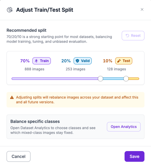
For this project, use the following split:
- 70% training
- 20% validation
- 10% testing
When creating the dataset version, review the split percentages and make any necessary adjustments before continuing.
Step 5: Apply Preprocessing and Augmentation
Before training the model, we need to prepare the images so they have a consistent format and introduce some realistic variation into the training data. Roboflow provides preprocessing and augmentation tools that make it easier to prepare the dataset without modifying the original images.
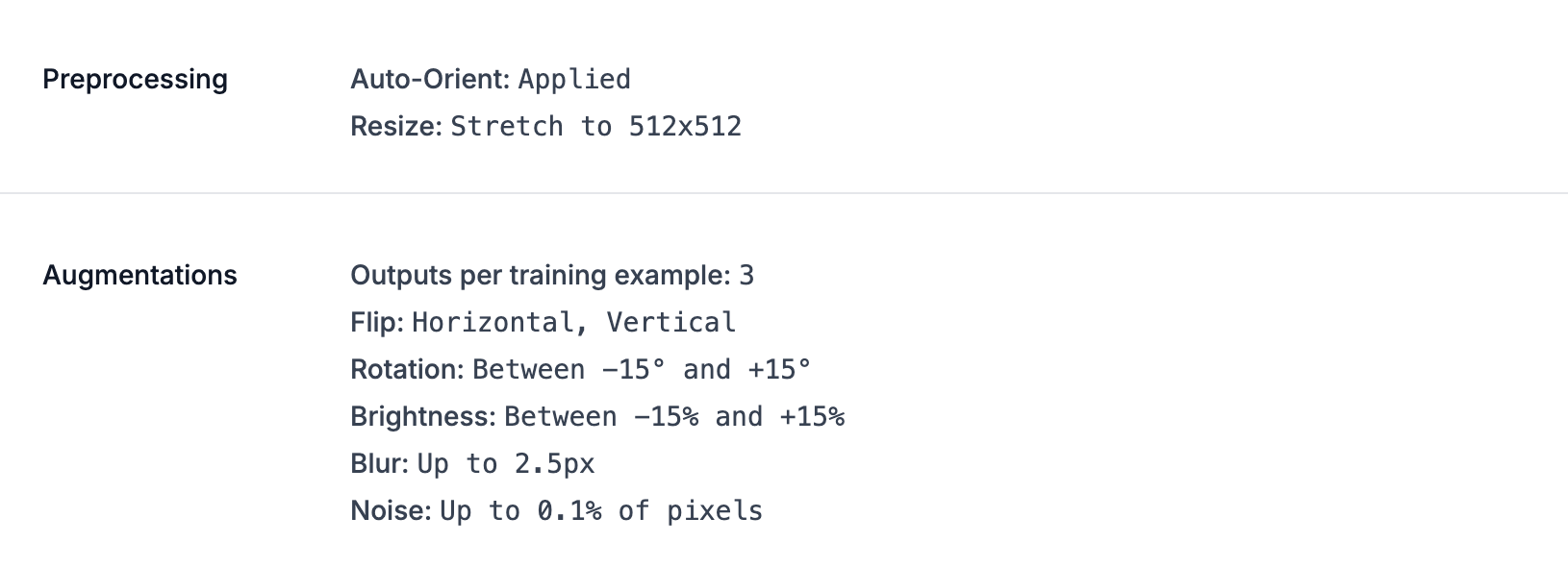
For preprocessing, apply the following:
- Auto-Orient: Corrects image orientation using the image's stored metadata.
- Resize: Stretches each image to 512 × 512 pixels so that the model receives images with a consistent input size.
For augmentation, set Outputs per training example to 3. This creates additional variations of the training images using the transformations below:
- Flip: Enable Horizontal and Vertical flips to help the model recognize defects regardless of their orientation within the image.
- Rotation: Set between -15° and +15° to simulate small changes in the camera or wood's orientation.
- Brightness: Set between -15% and +15% to account for differences in lighting conditions during image capture.
- Blur: Apply up to 2.5px of blur to simulate minor differences in image sharpness.
- Noise: Add noise to up to 0.1% of pixels to introduce small variations that can occur from camera sensors or image capture.
These augmentations add realistic variation to the training data while keeping the visual characteristics of the wood defects intact. This can help the model generalize to images that differ slightly from the examples it saw during training.
Once the settings are configured, click Generate to create the dataset version.
Step 6: Evaluate the Training Results
Once training is complete, Roboflow evaluates the model using the test set to measure how well it can detect and classify wood defects it has not seen during training.
The trained model achieved the following results:
| Metric | Score |
|---|---|
| mAP@50 | 70.2% |
| Precision | 74.0% |
| Recall | 66.2% |
| F1 | 69.9% |
The model achieved an mAP@50 of 70.2%, indicating that it was able to locate and classify the different wood defects with a reasonable level of accuracy. The 74.0% precision means that when the model predicted a defect, the prediction was correct about three-quarters of the time. The 66.2% recall shows that the model detected around two-thirds of the defects present in the test images.
The 69.9% F1 score provides a balance between precision and recall, giving us an overall measure of how consistently the model was able to identify the defects while limiting incorrect detections.
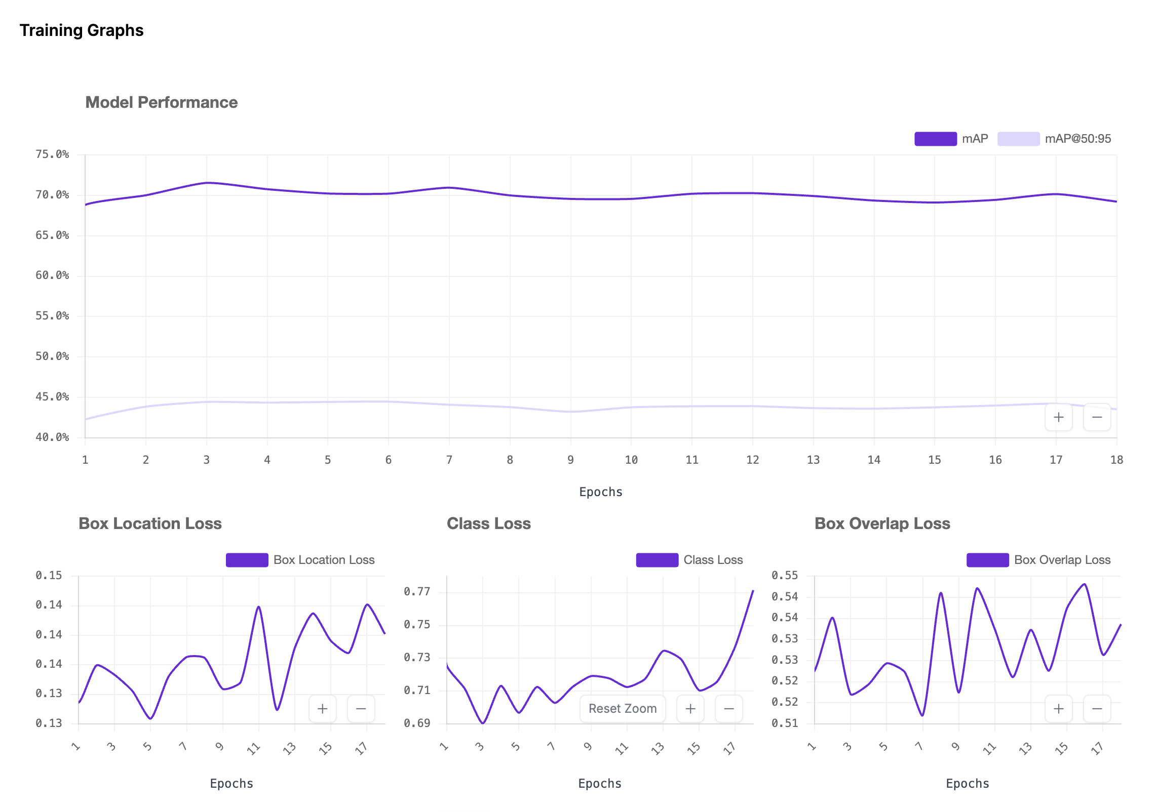
These results provide a solid starting point for demonstrating automated wood-defect inspection. However, they would not necessarily be sufficient for deploying the system in a production environment. In a real inspection system, missing a defect or incorrectly classifying one could affect downstream quality-control decisions.
It is also worth looking beyond the overall metrics and reviewing the model's per-class performance. Some of the five defect classes can have similar visual characteristics. For example, a knot with crack may be difficult to distinguish from a regular knot or crack depending on the appearance of the surrounding wood.
If certain classes perform worse than others, the model could be improved by adding more representative images for those classes, reviewing the annotations, or collecting images that better represent the conditions in which the system will eventually be used.
Step 7: Build the Wood Defect Detection Workflow
Once the model is trained, we can create a Roboflow Workflow to turn its predictions into a more complete inspection pipeline.
Go to the Workflows tab in your Roboflow dashboard and click Create Workflow. Select a blank Workflow. The Input and Output blocks will already be present.
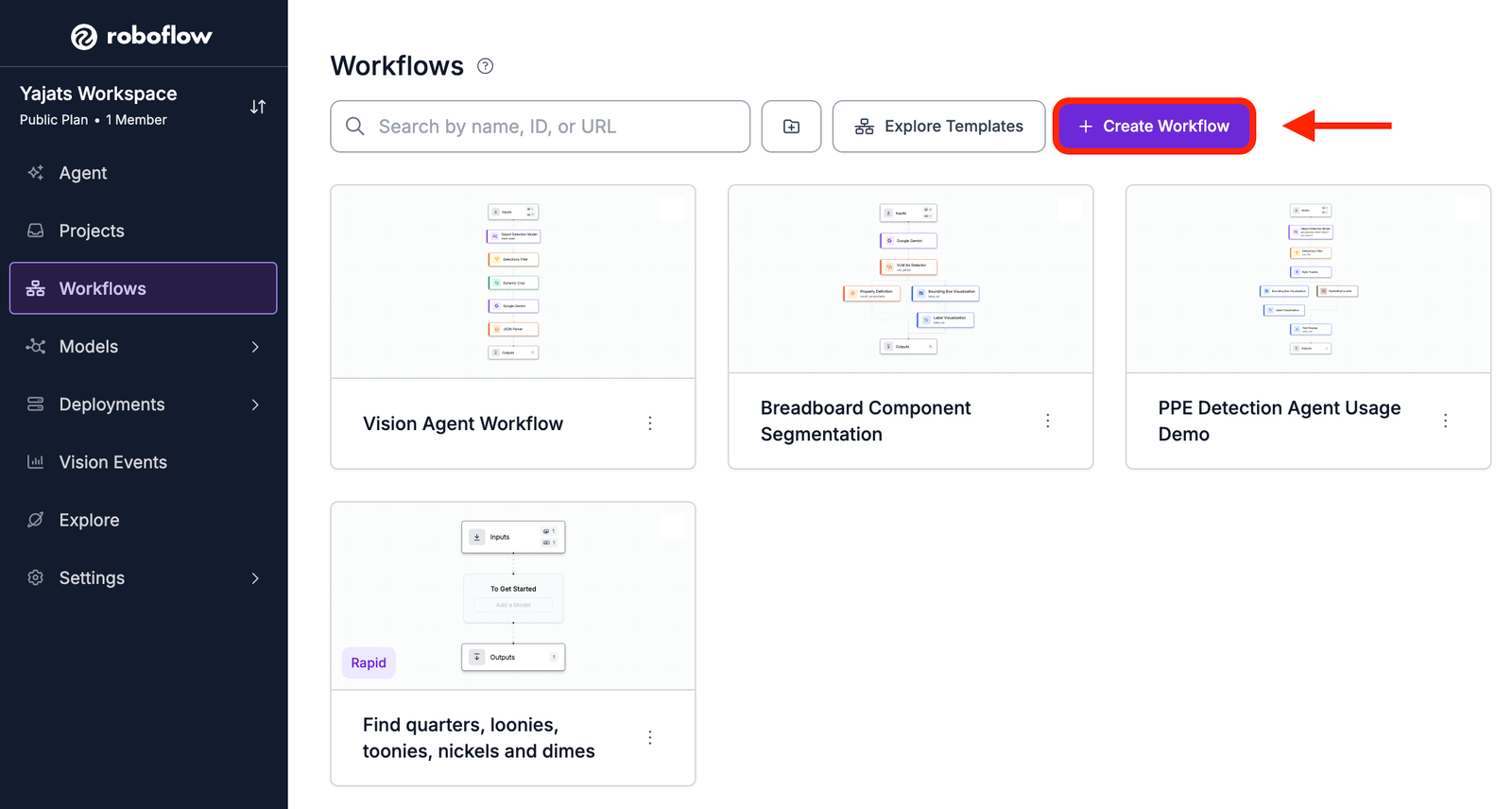
For this project, the Workflow will contain the following blocks:
- Object Detection Model
- Property Definition
- Bounding Box Visualization
- Label Visualization
- Text Display
The Object Detection Model block runs the trained RF-DETR model and produces the defect predictions. The Property Definition block uses those predictions to calculate the number of detected defects. The visualization blocks then make the predictions easier to interpret, while the Text Display block shows the total count on the final image.
This gives us a simple way to turn the model's raw predictions into an output that can be reviewed by someone inspecting the wood.
Block 1: Object Detection Model
Start by adding an Object Detection Model block. This is the part of the Workflow responsible for running the trained model on the input image.
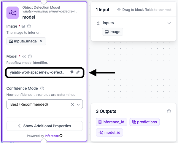
Click Add Block and search for Object Detection Model. Connect the block to the Image Input block and select your trained wood-defect-detection model from the model dropdown.
Set the image input to use the image supplied by the Workflow's Input block. You can also configure the confidence threshold (by changing the confidence mode to custom) to determine which predictions should be included in the Workflow.
Block 2: Property Definition
Next, add a Property Definition block. Rather than detecting anything itself, this block lets us extract information from the predictions produced by the model.
Connect it to the Object Detection Model and configure it as follows:
- Data: Select the predictions from the Object Detection Model.
- Operation: Select Count Items.
The resulting value represents the total number of defects detected in the image.
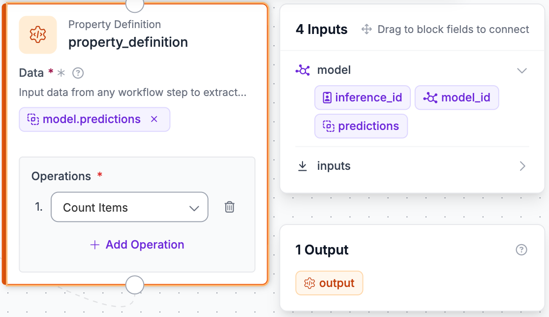
For instance, if the model identifies two cracks and one live knot, the Property Definition block will return a count of three.
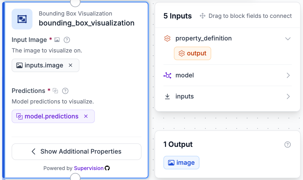
Block 3: Bounding Box Visualization
Now add a Bounding Box Visualization block. This block makes the model's predictions visible by drawing a box around each detected defect.
Configure it with:
- Image: The original input image
- Predictions: The predictions from the Object Detection Model
The block uses the coordinates returned by RF-DETR to determine the position and size of each bounding box.
This is particularly useful when testing the model because it allows you to compare the model's predictions directly with the defects visible in the original image.
Block 4: Label Visualization
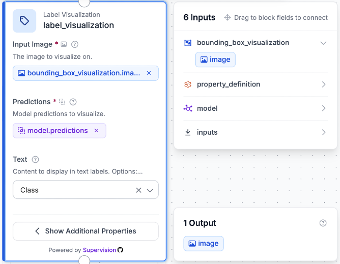
Next, add a Label Visualization block and connect it after the Bounding Box Visualization block.
Use the following configuration:
- Image: The output from Bounding Box Visualization
- Predictions: The predictions from the Object Detection Model
Configure the displayed text to include the predicted class name. The resulting image will show the defect type alongside each detected region.
Depending on the prediction, the labels could identify defects such as crack, dead_knot, holes, knot_with_crack, or live_knot.
This makes the output more informative than simply drawing boxes, since someone reviewing the image can immediately see what type of defect the model believes it has found.
Block 5: Text Display
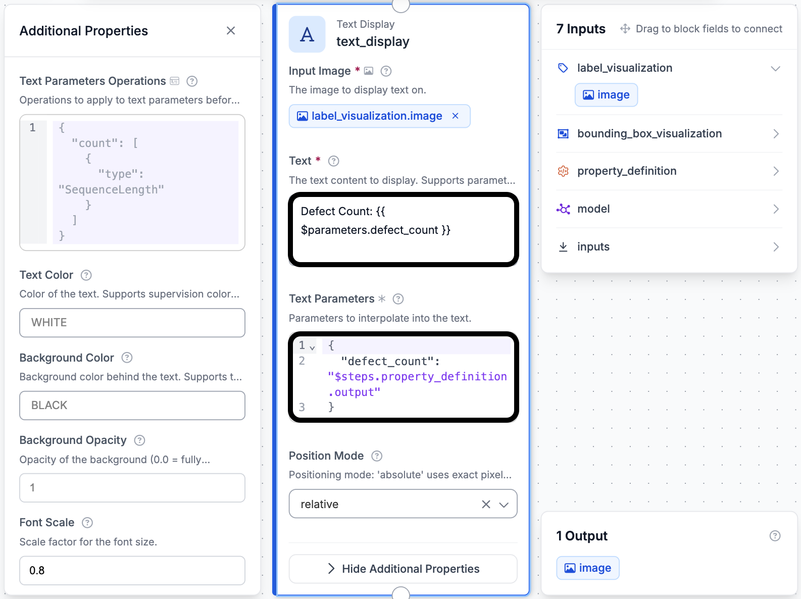
The final processing block is Text Display. We will use this block to place the total number of detected defects on the image.
Connect Text Display after Label Visualization and use the labelled image as its input.
Set the displayed text to:
Defect Count: {{ $parameters.defect_count }} Then reference the value produced by the Property Definition block in the text parameters:
{
  "defect_count": "$steps.property_definition.output"
}
Set the position mode to relative and choose a location that keeps the count visible without covering any important defect detections.
Once the blocks are connected and configured, set the Workflow Output to return the image produced by Text Display and click Save Workflow.
Step 8: Test the Workflow
With the Workflow saved, click Test in the upper-right corner of the editor.
Upload an image containing one or more wood defects and run the Workflow. The resulting image should show the detected defects with their bounding boxes and class labels, along with the total number of detections.
When reviewing the output, pay attention to both correct and incorrect predictions. A correct detection should have a bounding box that covers the actual defect and a class label that matches the visible defect.
If the Workflow is producing too many false detections, try increasing the confidence threshold in the Object Detection Model block. If visible defects are being missed, lowering the threshold may allow more predictions to pass through.
Test the Workflow with several images rather than relying on a single example. In particular, try images containing different defect classes and different wood textures so you can get a better idea of how the model behaves across the dataset.
You can try the complete wood defect detection Workflow here.
Conclusion
Automating this type of inspection can make it easier to consistently monitor wood surfaces. The approach can also be extended beyond simple defect detection. For example, detected defects could eventually be used as part of a larger quality-control system for sorting, grading, or flagging pieces of wood for additional inspection.
The performance of the system will ultimately depend on how closely the training data represents the environment where the model is used. Adding more images from real production conditions, improving annotations, and collecting examples of difficult-to-detect defects can all help make the model more reliable.
Further reading:


Cite this Post
Use the following entry to cite this post in your research:
Yajat Mittal. (Aug 12, 2026). Wood Defect Detection with Computer Vision. Roboflow Blog: https://blog.roboflow.com/wood-surface-inspection/