
This tutorial builds a single-axis vision-guided camera system using a USB webcam, an Arduino-controlled servo, and a Roboflow Workflow that runs real-time object detection over WebRTC. A Python script converts per-frame detections into pan commands using a zone-based approach, and smooth motion is handled by a smootherstep easing function on the Arduino. The same core pattern scales to multi-axis tracking, PTZ cameras, and custom-trained models for specific subjects in broadcast, lecture capture, or inspection contexts.
Camera control is the process of directing a physical camera where it points, how it moves, and when it holds position in response to what is happening in the scene. Computer vision adds an automated layer to that process, where a model analyzes the video frame, identifies a subject of interest, and generates the positional information needed to move the camera.
The control loop is straightforward. Every frame, the system determines where the subject is relative to the frame center. The answer drives a movement decision such as pan, tilt, hold, track or zoom. That decision is sent to the physical camera hardware. This loop runs continuously, keeping the subject framed without manual input. Here are some example of camera control:
- Live sports broadcasting: cameras that track a ball or player across a court or pitch, holding the subject centered as they move
- Studio and interview recording: cameras that keep a presenter or speaker in frame, recentering automatically when they shift position
- Lecture and training capture: tripod-mounted cameras that follow an instructor across a room or coaching area without an operator present
- Inspection and surveillance: cameras that move to a detected object or anomaly and hold position for closer examination
In this tutorial, we build a simple single-axis automated camera system using a USB webcam mounted on a servo controlled by an Arduino. A Roboflow Workflow performs real-time object detection over WebRTC, while a Python script converts detections into pan commands.
The system uses a zone-based approach, moving the camera only when the subject leaves the centre region. Smooth motion is achieved using a smootherstep easing function on the Arduino. The goal is to demonstrate a practical, low-latency camera control system driven by computer vision. Here's the system output.
Output of System
So, let's get started.
Selecting the right camera is foundational to the success of any computer vision project. Download the Choosing Cameras and Lenses for Computer Vision report.
Computer Vision in Broadcast Camera Control
By detecting players, balls, and motion in real time, and linking those detections to physical camera systems, it is now possible to build camera systems that can move automatically and keep the subject in frame.
As just one example, Fletcher Sports, working with Roboflow, built an AI-powered system that can recognize and track fast-moving players across multiple live video feeds, guiding the camera behavior. This system was used at both Wimbledon and the US Open to deliver full-court coverage.
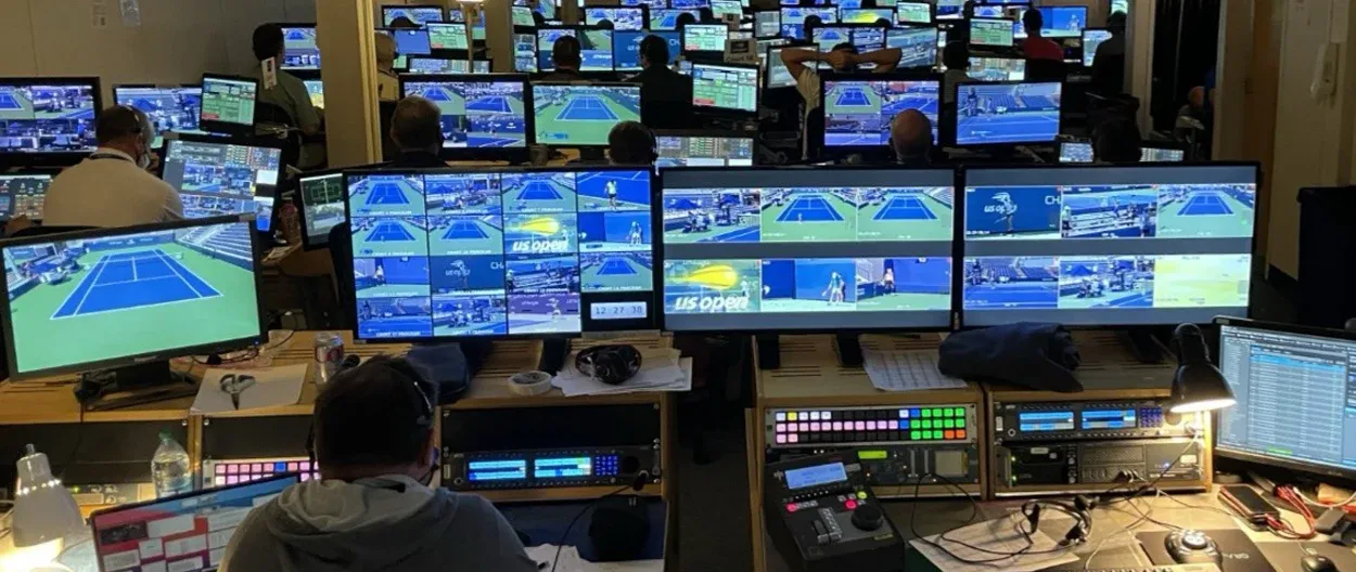
This shows a complete pipeline in practice:
- Computer vision detects and tracks players in real time
- The system calculates where the subject is in the frame
- Camera hardware (robotic pan/tilt systems) adjusts automatically
- The result is a stable, centered broadcast shot without manual control
The scale of this deployment highlights how mature the technology has become:
- 56 cameras controlled across 14 courts
- Over 1 billion frames processed per day
- Multiple production units replaced by a centralized operations setup
Building a Camera Control Application with Roboflow
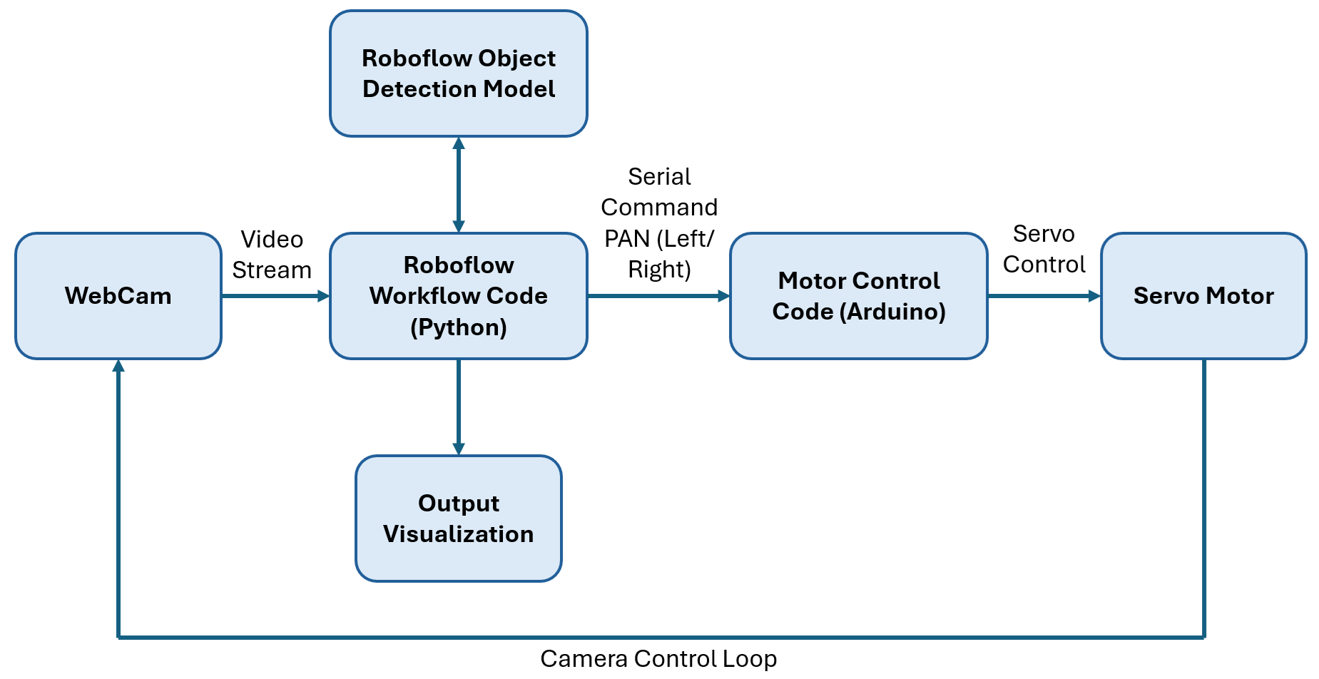
In this tutorial, we will build a simple single-axis automated camera system using a USB webcam mounted on a servo motor controlled by an Arduino. A Roboflow Workflow performs real-time object detection over WebRTC, and a Python script reads the bounding box position and sends pan commands to the servo. The following image show the system architecture.
The control logic follows a zone-based approach. Instead of continuously adjusting the camera for every small movement, the frame is divided into three regions: left, centre, and right. As long as the detected subject remains within the centre zone, the camera does not move. When the subject drifts into the left or right zone, the system triggers a movement in that direction to bring the subject back to the centre.
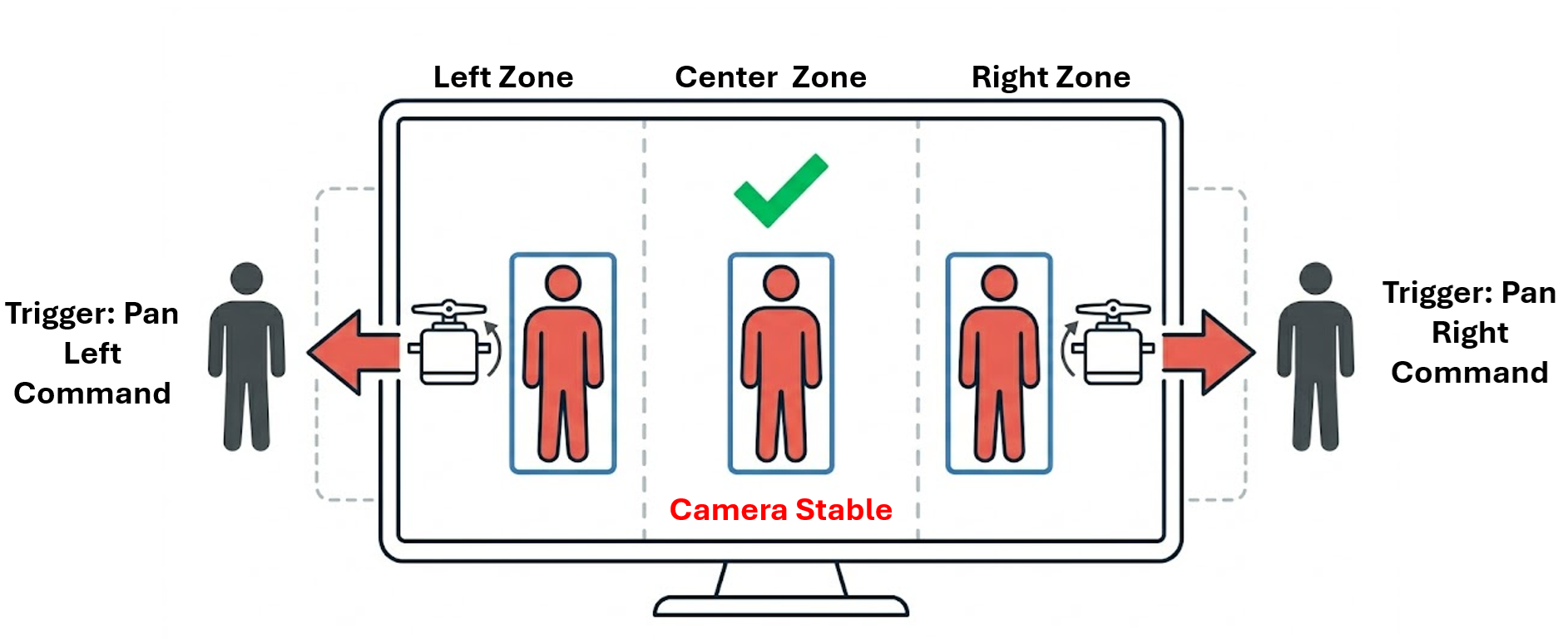
This approach keeps the system stable and avoids unnecessary jitter. It also reduces the number of control commands, making the system more efficient and easier to implement on simple hardware like an Arduino. To make the motion smoother, the Arduino uses a smootherstep easing function. This converts each discrete movement command into a gradual transition, so the camera movement feels natural rather than abrupt.
The system runs in real time. As the subject moves, the camera responds immediately while maintaining stable and smooth motion. The goal of this example is to demonstrate how computer vision can be directly connected to physical camera control in a practical, low-latency setup.
How the Control Loop Works
At a high level, every automated camera system follows the same control loop:
- The camera captures a frame (or continuous video stream)
- A detection model identifies the subject and returns a bounding box
- The centre of the bounding box is compared with the centre of the frame
- The difference between the two (error) is calculated
- A control signal moves the camera to reduce this error toward zero
In our implementation, this loop runs continuously, allowing the camera to react instantly to changes in the scene. This is the same core principle used in real-world systems, whether it is a servo-mounted webcam in this tutorial or a robotic broadcast camera tracking athletes on a tennis court.
Hardware Requirements
- USB webcam (any standard webcam)
- SG90 or MG90S servo motor (standard 9g hobby servo)
- Arduino Uno
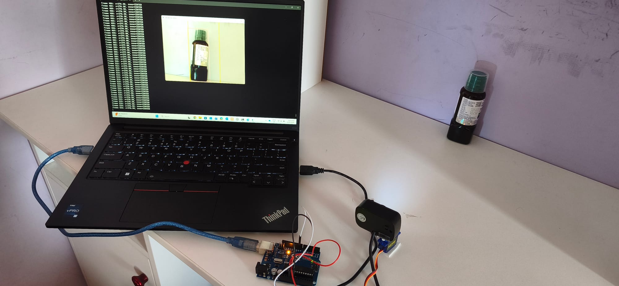
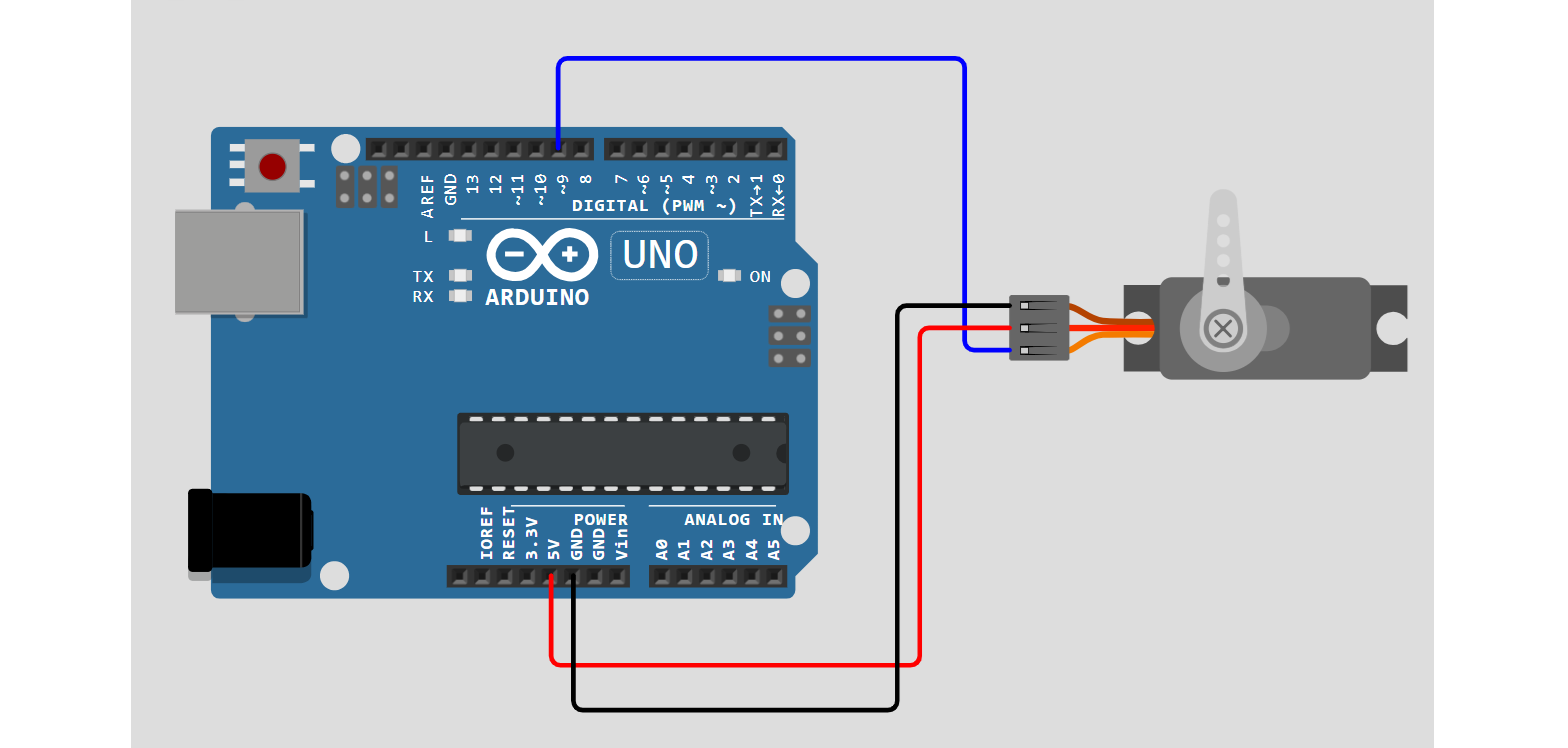
Here's the setup that I am using.
Use the following circuit diagram to connect servo to Arduino UNO.
Step 1: Building the Roboflow Workflow
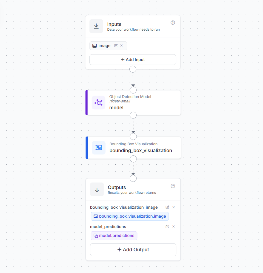
To enable real-time camera control, we first need a workflow that can detect our subject reliably from a live video stream. In this example, we use a Roboflow Workflow with an RF-DETR model to detect a simple object class, in this case a bottle. This keeps the setup easy to test while still demonstrating the full control loop.
The workflow has input block, which receives frames from the live video stream. When deployed with WebRTC, this input continuously processes frames in real time.
Next, add an Object Detection block that uses RF-DETR-Small public model.
- The model detects objects and returns bounding boxes
- In this example, I applied a class filter to only detect
"bottle" - This ensures the system responds only to the target object and ignores everything else
This filtered detection is what drives the camera movement logic later in the pipeline. A Bounding Box Visualization block is added to overlay detections on the frame. This is useful for debugging and confirming that the system is correctly tracking the object in real time. The workflow returns two outputs:
model_predictions→ structured detection data (bounding box, class, confidence)bounding_box_visualization_image→ annotated frame for display
The workflow deployment Python script uses model_predictions to compute object position and send commands to the servo.
Step 2: Flash the Arduino Sketch
The Arduino receives simple serial commands from the Python script.L moves the camera left and Rmoves it right. Each command changes the servo angle by a fixed step. Instead of jumping directly to the new position, we move the servo gradually to make the motion smooth and stable.
#include <Servo.h>

Servo panServo;

const int SERVO_PIN   = 9;
int servoAngle        = 90;
const int STEP_ANGLE  = 8;
const int MOTION_STEPS = 50;
const int STEP_DELAY  = 5;

void setup() {
  Serial.begin(115200);
  panServo.attach(SERVO_PIN);
  panServo.write(servoAngle);
  delay(500);
}

float smootherstep(float t) {
  return t * t * t * (t * (t * 6.0 - 15.0) + 10.0);
}

void moveServoSmooth(int targetAngle) {
  int startAngle = servoAngle;
  int delta = targetAngle - startAngle;

  for (int i = 0; i <= MOTION_STEPS; i++) {
    float t = (float)i / (float)MOTION_STEPS;
    float eased = smootherstep(t);
    panServo.write(startAngle + (int)(delta * eased));
    delay(STEP_DELAY);
  }

  servoAngle = targetAngle;
  panServo.write(servoAngle);
}

void loop() {
  if (Serial.available() > 0) {
    String cmd = Serial.readStringUntil('\n');
    cmd.trim();

    if (cmd == "L") {
      int target = max(0, servoAngle - STEP_ANGLE);
      moveServoSmooth(target);
    }
    else if (cmd == "R") {
      int target = min(180, servoAngle + STEP_ANGLE);
      moveServoSmooth(target);
    }
  }
}
This approach avoids sudden jumps and gives the camera a natural movement. The motion is controlled using a smoothing function instead of a linear movement.

Here, t moves from 0 to 1 across the motion steps. Instead of moving at a constant speed, the servo follows an S-shaped curve. It starts slowly, speeds up in the middle, and slows down again before stopping. The servo position at each step is computed as:

where,

This makes the camera movement smooth and stable, which is important for any vision-guided system.
Step 3: Deploying the Camera Control System Workflow
To connect detection with physical camera movement, we use a Python script that runs alongside the Roboflow Workflow and communicates with the Arduino over serial. The workflow streams video using WebRTC and returns object detections in real time, while the script reads those detections and decides when the camera should move.
The system follows a zone-based centering approach. The frame is divided into three horizontal zones using two fixed thresholds. For a 640-pixel-wide frame, the centre zone spans from x=200 to x=440. This creates a stable band around the middle of the frame where the object is considered properly framed. The system uses the bounding box centre returned by Roboflow workflow to determine where the object is located in each frame.
- if
x < 200→ LEFT zone → sendRto move the camera right - if
x > 440→ RIGHT zone → sendLto move the camera left - if
200 <= x <= 440→ CENTRE zone → no movement
The key idea is simple. As long as the object stays inside the centre band, the camera does nothing. When the object moves outside this band, the system issues a command to bring it back toward the centre.
To keep the movement stable, the script waits for the object to remain in the same zone for a few frames before acting, and also applies a short delay between commands. This avoids jitter and ensures smooth camera behaviour. Below is the full deployment script.
import cv2, serial, time
from inference_sdk import InferenceHTTPClient
from inference_sdk.webrtc import WebcamSource, StreamConfig

# Serial connection to Arduino
SERIAL_PORT = "COM4"
arduino = serial.Serial(SERIAL_PORT, 115200, timeout=1)
time.sleep(2)

# Roboflow setup
client = InferenceHTTPClient.init(
    api_url="https://serverless.roboflow.com",
    api_key="YOUR_API_KEY"
)

source = WebcamSource(device_id=1, resolution=(640, 640))

config = StreamConfig(
    stream_output=["bounding_box_visualization_image"],
    data_output=["model_predictions"],
    processing_timeout=3600,
    requested_plan="webrtc-gpu-medium",
    requested_region="us"
)

session = client.webrtc.stream(
    source=source,
    workflow="YOUR_WORKFLOW",
    workspace="YOUR_WORKSPACE",
    image_input="image",
    config=config
)

# Zone thresholds
LEFT_EDGE_LIMIT  = 200
RIGHT_EDGE_LIMIT = 440

ZONE_CONFIRM_FRAMES = 2
COMMAND_COOLDOWN    = 0.35
MAX_MISSED_FRAMES   = 1

last_command_time = 0
missed_frames     = 0
current_zone      = "CENTER"
candidate_zone    = None
candidate_count   = 0

def get_zone(x):
    if x < LEFT_EDGE_LIMIT: return "LEFT"
    if x > RIGHT_EDGE_LIMIT: return "RIGHT"
    return "CENTER"

@session.on_data()
def on_data(data, metadata):
    global missed_frames, current_zone, candidate_zone, candidate_count, last_command_time

    predictions = data.get("model_predictions", {}).get("predictions", [])

    if not predictions:
        missed_frames += 1
        if missed_frames >= MAX_MISSED_FRAMES:
            candidate_zone = None
            candidate_count = 0
            current_zone = "CENTER"
        return

    missed_frames = 0
    obj_x = predictions[0]["x"]
    zone = get_zone(obj_x)

    if zone == "CENTER":
        candidate_zone = None
        candidate_count = 0
        current_zone = "CENTER"
        return

    if zone == candidate_zone:
        candidate_count += 1
    else:
        candidate_zone = zone
        candidate_count = 1

    now = time.time()

    if (candidate_count >= ZONE_CONFIRM_FRAMES and
        (now - last_command_time) >= COMMAND_COOLDOWN and
        zone != current_zone):

        cmd = b"R\n" if zone == "LEFT" else b"L\n"
        arduino.write(cmd)

        last_command_time = now
        current_zone = zone
        candidate_zone = None
        candidate_count = 0

session.run()
arduino.close()
cv2.destroyAllWindows()
This script completes the pipeline from detection to action. The camera observes the scene, the model identifies the object, and the system adjusts the camera position in real time to keep the subject centred.
What You Can Build Next
The zone-based system built here is a strong starting point. The core pipeline of object detection, bounding box position, control logic, and smooth servo motion is already capable of practical camera control. From here, you can extend the system toward more advanced and production-ready setups.
Two-Axis Pan and Tilt
The current system controls only horizontal movement. This can be extended by adding a vertical motion using a pan-tilt mount. This allows smoother and more precise tracking as the camera continuously adjusts to keep the subject centered.
Network-Controlled PTZ Camera
For advanced setups, the servo-based system can be replaced with a PTZ Tracking (ONVIF) where computer vision directly controls pan, tilt, and zoom. The system processes a live video stream, detects the subject, and continuously updates the camera position to keep the subject in view.
In this approach, each frame is analyzed to locate the subject, and its position relative to the centre of the frame is used to decide how the camera should move. If the subject shifts left or right, the camera pans accordingly. If it moves up or down, the camera adjusts tilt. When the subject appears small in the frame, the system can also zoom in to maintain a clear view.
Pan and tilt tracking using PTZ camera
The camera movement is not based on fixed steps, but on continuous feedback from the detected position. Small movements near the centre are ignored to avoid jitter, while larger shifts trigger smooth adjustments. When zoom is applied, motion is stabilized to prevent sudden changes, and once the subject is no longer detected, the camera can return to a default position.
Zoom behavior and full PTZ tracking using PTZ camera
This approach allows a single camera to cover a large area while still focusing on important details. Compared to a simple servo setup, it provides smoother motion, higher precision, and integrated zoom, making it suitable for real-world monitoring and production environments.
For help building this system, refer to our guide on How to Control a PTZ Camera with Roboflow Workflows.
Computer Vision Assisted Camera Control in Media and Broadcast
Automated camera control using computer vision has many applications across media and broadcast production. The same pipeline of detection, position understanding, and camera movement can scale from a single unattended setup to multi-camera deployments.
- Live Sports Coverage: Automated cameras can follow a match continuously by tracking the ball or a key player and keeping them in frame. When the subject moves out of view, the system reacquires it automatically.
- Lecture and Training Capture: An automated camera can be used to track a presenter or coach during a session. The system keeps the subject centred and adjusts when they move across the stage or room.
- Studio and Interview Recording: In studio setups, the system can maintain stable framing of a speaker. When the subject shifts position or leans, the camera adjusts smoothly to recenter them. This results in clean and professional-looking footage without manual intervention.
Assisted Camera Control Conclusion
Computer vision makes it possible to build camera systems that can detect a subject, understand its position, and adjust framing automatically in real time. In this tutorial, we built a complete pipeline from detection to camera movement. While the setup is simple, the same idea scales to more advanced systems, from multi-axis tracking to full PTZ cameras used in real production environments. If you want to extend this further, you can train custom models for your use case, improve tracking logic, or connect the system to more advanced camera hardware. The core idea remains the same. Use vision to understand the scene, and use that understanding to control the camera.
Start building your own vision-guided camera system using Roboflow and adapt it to your specific application.
How can I automate camera control with computer vision?
You can automate camera control by using a computer vision model to continuously detect a subject in a live video feed and calculate its position relative to the center of the frame. Based on this position, a control script sends real-time directional commands to physical camera hardware, such as an Arduino-controlled servo or a PTZ mount, to smoothly adjust the camera and keep the subject perfectly framed.
Cite this Post
Use the following entry to cite this post in your research:
Timothy M. (Apr 20, 2026). Automate Camera Control with Computer Vision. Roboflow Blog: https://blog.roboflow.com/automate-camera-control/