
Detect injection molding defects automatically by training a Roboflow RF-DETR model on labeled defect images, then deploying it in a Roboflow Workflow that draws bounding boxes around cracks, breaks, and surface contamination. Gemini 2.5 Pro reviews each detection and writes a one-line inspection note, and the same pipeline adapts to medical injection-molded parts such as syringes and IV connectors.
Injection molding is one of the most widely used manufacturing processes, producing millions of plastic components every day. While the process is highly efficient, defects can still occur, leading to material waste, increased production costs, and additional quality-control effort.
The impact is significant. Industry estimates suggest that injection molding defects account for up to $12 billion in annual waste worldwide.
In this tutorial, we'll build a molding defect detection system using Roboflow. We'll train an RF-DETR model, deploy it with a Roboflow workflow, and integrate Gemini 2.5 Pro to generate AI-powered inspection observations.
The final system can:
- Detect defects from images
- Generate AI-powered inspection observations
- Produce annotated images with visual detections
- Demonstrate a workflow that can be adapted for medical manufacturing applications
Injection Molding Defect Detection for Medical Components
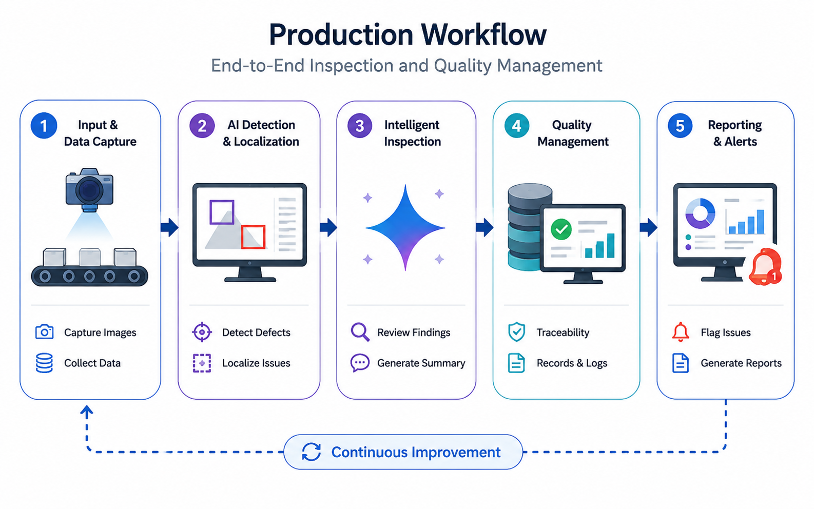
Here's the workflow we'll build. While the dataset used in this article contains general quality defects on molded components, the same workflow can be applied to medical-specific components and inspection requirements.
Step 1: Prepare the Dataset
For this project, we use the Molding Defect Detection dataset from Roboflow Universe. The dataset contains annotated defect regions across five classes:
- MOLDING_BREAK
- MOLDING_CRACK
- MOLDING_DEFECT
- MOLDING_POLLUTION
- MOLDING_POOR
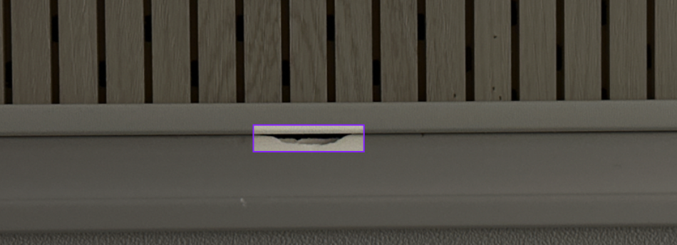
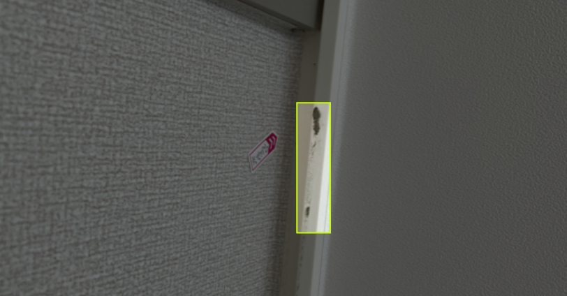
Before training, we first remove all images that belong to the null class. Since the goal of this project is to train a model to localize and classify visible quality defects on molded components, we'll use only the images that contain annotations.
Here are a few examples from the dataset:
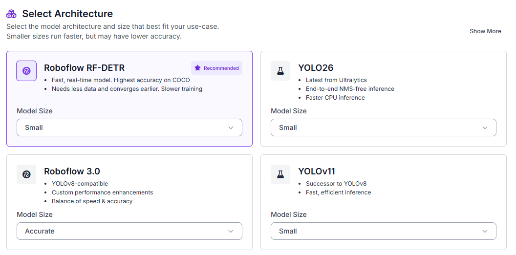
Once the dataset has been cleaned, fork it into your Roboflow workspace. Next, navigate to the Train tab and select Custom Training. From the available architectures, choose RF-DETR and set the model size to Small.
Before starting training, generate a new dataset version and use a 70/15/15 split for training, validation, and testing.
Enable the following preprocessing steps:
- Auto-orientation
- Resize (512×512)
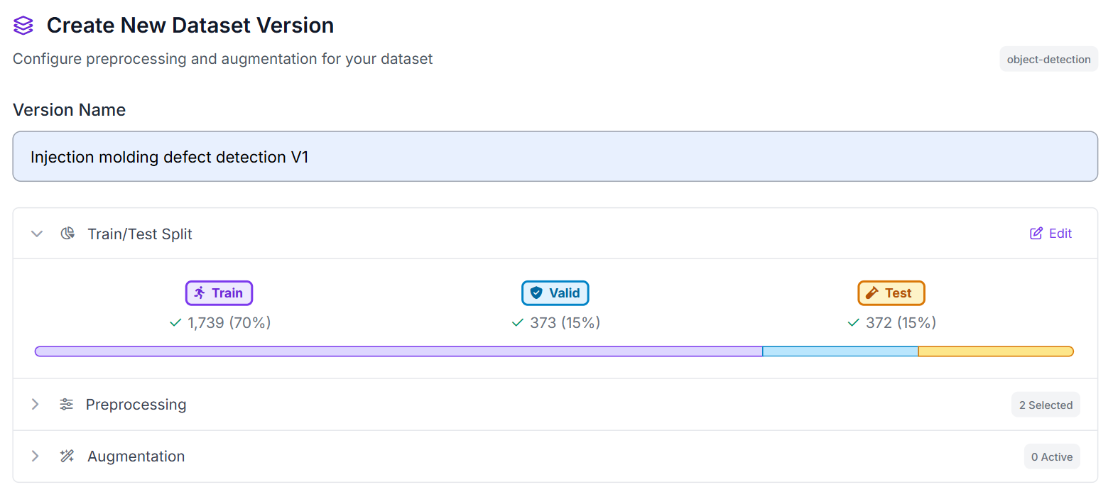
These preprocessing steps ensure all images have a consistent orientation and resolution before being used for training.
Step 2: Train the RF-DETR Model
Once training begins, RF-DETR learns to identify and localize the annotated defect classes directly from the training images. Unlike a classification model that only predicts whether a defect is present, RF-DETR returns bounding boxes that indicate where defects appear within an image.
This makes the model particularly useful for inspection workflows. Instead of receiving a simple defect prediction, inspectors can see the exact location of the detected issue and quickly review the affected area.
After training completes, the model is ready to be deployed in a Roboflow Workflow. We'll use it as the foundation for our automated inspection pipeline and later integrate Gemini 2.5 Pro to generate inspection observations based on the model's detections.
Step 3: Build the Roboflow Workflow
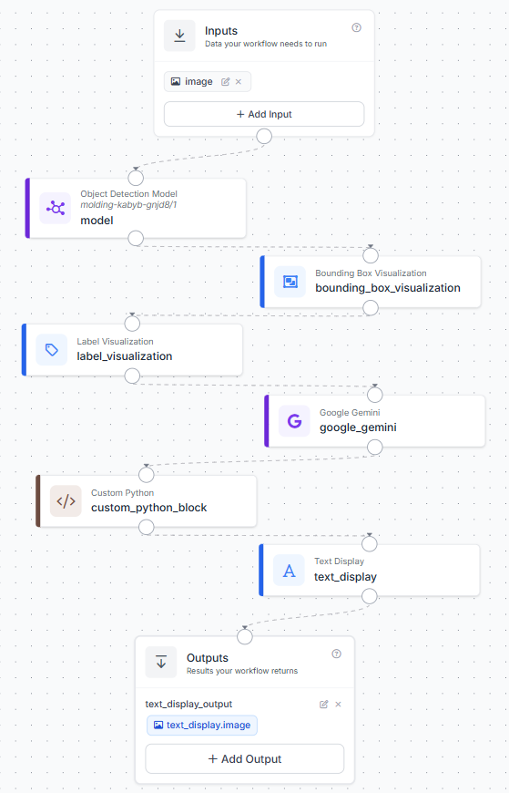
After training the RF-DETR model, create a Roboflow Workflow that connects defect detection, visualization, Gemini inspection, text formatting, and final image output.
The workflow contains the following blocks:
- Input: receives the molded component inspection image.
- RF-DETR Object Detection Model: detects visible defect regions on the molded component.
- Bounding Box Visualization: draws bounding boxes around detected defect regions.
- Label Visualization: adds class labels to the detected regions.
- Google Gemini: inspects the detected regions and generates a short quality-control observation.
- Custom Python Block: formats the Gemini output into a clean inspection summary.
- Text Display: overlays the formatted inspection summary on the annotated image.
- Outputs: returns the final image with bounding boxes, labels, and inspection text.
This workflow keeps each stage easy to understand. RF-DETR finds the defect regions, the visualization blocks make the detections visible, Gemini describes the detected area, and the formatter prepares the text for display on the final image.
The completed workflow should resemble the configuration shown below.
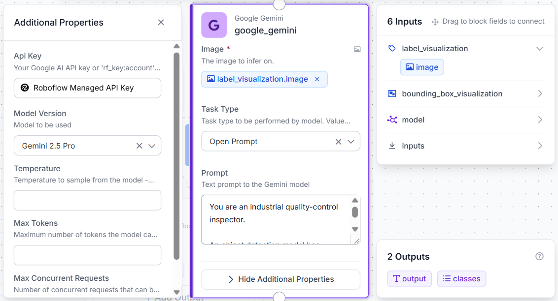
Step 4: Configure the Gemini Inspection Block
The Gemini block is used after the object detection and visualization blocks. At this stage, the model has already detected the potential defect regions, so Gemini does not need to search for new defects. Its job is to inspect the highlighted areas and generate a short observation.
Connect the Label Visualization image output to the Gemini image input. This gives Gemini the annotated image with the detected regions and labels visible.
Use a prompt like this:
You are an industrial quality-control inspector.

An object detection model has already identified defect regions in the image and provided defect class labels.

Do not search for additional defects.
Do not perform defect detection.
Only inspect and describe the defect regions identified by the model.

Using the provided detections and the image:

Examine the defect region(s) highlighted by the model.
Describe what is visually visible inside the detected region.
Mention the detected class label.
Mention the approximate location of the detected region.
Keep the response to a single concise sentence.
Maximum 15 words.
Do not speculate about manufacturing causes.
Do not explain the inspection process.

Examples:

MOLDING_BREAK detected near the upper edge, showing a visible chipped section; review required.

MOLDING_CRACK detected at the top-right corner, showing a narrow surface crack; review required.

MOLDING_POLLUTION detected in the center region, showing visible surface contamination; review required.

If no detections are present, return:

No visible defects detected; inspection passed.

Return only the inspection summary sentence.
This keeps Gemini focused on inspection commentary rather than detection. The object detection model decides where the defect is; Gemini simply turns that detection into a readable quality-control observation.
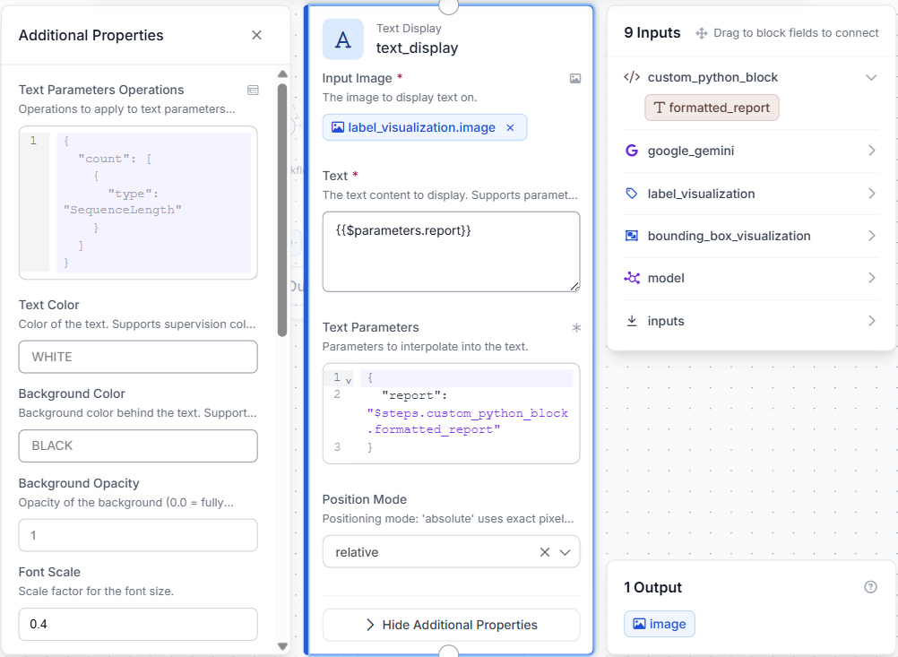
Step 5: Format the Inspection Output
Next, add a Custom Python Block after Gemini. This block receives the Gemini response and formats it for display on the final annotated image.
Use the Python block to clean the Gemini text and pass back only the inspection summary:
def run(self, gemini_output, predictions):
    import re

    report = str(gemini_output or "").strip()
    report = re.sub(r"```.*?```", "", report, flags=re.DOTALL)
    report = report.replace("**", "")
    report = re.sub(r"\s+", " ", report)

    return {"formatted_report": report}
Then connect the formatter output to the Text Display block.
The Text Display block overlays the inspection sentence on top of the annotated image. This creates a final output that includes both the visual model detections and the Gemini-generated inspection summary.
Step 6: Test the Workflow
With the workflow configured, run inference on several molded component images. Test images with clear defects, smaller defects, and images where the detected region is difficult to inspect.
For each test image, review:
- The bounding box around the detected defect.
- The class label applied by the model.
- The Gemini-generated inspection sentence.
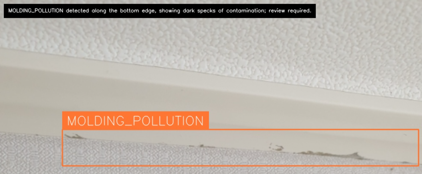
A typical output should show the detected defect region with a label, along with a short inspection sentence placed on the image.
Applying the Workflow to Medical Component Inspection
While this tutorial uses a dataset of visible defects on molded components, the same workflow can be adapted for medical manufacturing by training the model on medical-specific parts and defect categories.
In a production environment, cameras could be installed at key inspection points to automatically examine components as they move through the manufacturing process. Examples include syringes, IV connectors, diagnostic cartridges, inhaler housings, and other injection-molded medical devices.
A typical deployment could involve:
- Image Acquisition: Industrial cameras capture images of medical components after molding, assembly, or packaging.
- Defect Detection: RF-DETR identifies visible defect regions and classifies them based on the training data.
- Inspection Review: Gemini reviews the detected regions and generates concise inspection observations.
- Quality Documentation: Inspection results are stored for traceability, batch reporting, and audit purposes.
- Operator Action: Components flagged during inspection can be reviewed, reworked, or removed from the production line.
The overall workflow remains unchanged. RF-DETR continues to detect defect regions, Gemini provides inspection observations, and the final output combines visual detections with human-readable quality information. By replacing the training dataset with medical-specific images, manufacturers can use the same approach to support automated inspection of medical injection-molded components.
Medical Injection Molding Defect Detection with Roboflow Agent
If you'd rather not add each block by hand, use Roboflow Agent. Instead of configuring blocks one at a time, you describe the pipeline you want in plain text and the Agent builds it for you. Here's an example:
Injection Molding Defect Detection for Medical Components Conclusion
Our final system highlights detected defect regions and generates concise inspection summaries directly on the image. While the dataset used here contains general defects on molded components, the same approach can be applied to medical manufacturing by training on medical-specific parts and defect categories.
Further reading:
Cite this Post
Use the following entry to cite this post in your research:
Mostafa Ibrahim. (Jun 29, 2026). Injection Molding Defect Detection for Medical Components. Roboflow Blog: https://blog.roboflow.com/injection-molding-defect-detection-for-medical-components/