
Humans pretty much never think about camera calibration. Your brain automatically corrects imperfections you see: Straight lines stay straight. Objects stay the right size. Distance just “makes sense.”
Vision AI doesn’t automatically have that experience. A camera turns the 3D world into a flat 2D image. Along the way, lenses bend light, sensors shift coordinates, and perspective warps reality. To a model, that distortion is the world, unless you teach it otherwise.
That’s where camera calibration comes in. Camera calibration is how you teach a vision system the true geometry of the world. It defines:
- Where the camera is
- How it’s oriented
- How the lens bends light
- How pixels map back to real-world measurements
Without calibration, your model still runs, but it’s guessing.
In this guide, you’ll learn what camera calibration really is, how intrinsic and extrinsic parameters define a camera, and how lens distortion impacts your models. You'll also see step by step how to calibrate with OpenCV, and how to deploy those parameters directly into a Roboflow Workflow for production inference. Let's get started.
The Importance of Vision AI Camera Calibration
Calibrating a camera is essential for any computer‑vision application that requires metric information about a scene. Vision AI models such as YOLO or RF-DETR need undistorted inputs to interpret object size, shape, and distance correctly. Camera calibration is important for the following reasons:
- It helps correct distortions and perspective shifts so that straight lines in the world remain straight in the image and objects appear at the right position and size. This improves the accuracy of computer vision tasks like detection, tracking, and pose estimation tasks.
- It enhances depth estimation and distance measurements, which are critical for stereo vision, structure‑from‑motion and 3D reconstruction. Misaligned cameras (e.g. in stereo rigs or multi‑camera systems) lead to incorrect depth perception.
- It enables sensor fusion and robotics. In autonomous vehicles, drones, and industrial robots, calibration allows cameras to be fused with LiDAR or IMU data for accurate navigation and obstacle avoidance. Poor calibration causes misinterpretation of distances and can lead to safety issues.
Because camera properties can change over time due to temperature, vibration, or lens adjustments, cameras need to be recalibrated regularly, especially in high-precision environments or whenever the camera is repositioned.
What Does Camera Calibration Mean?
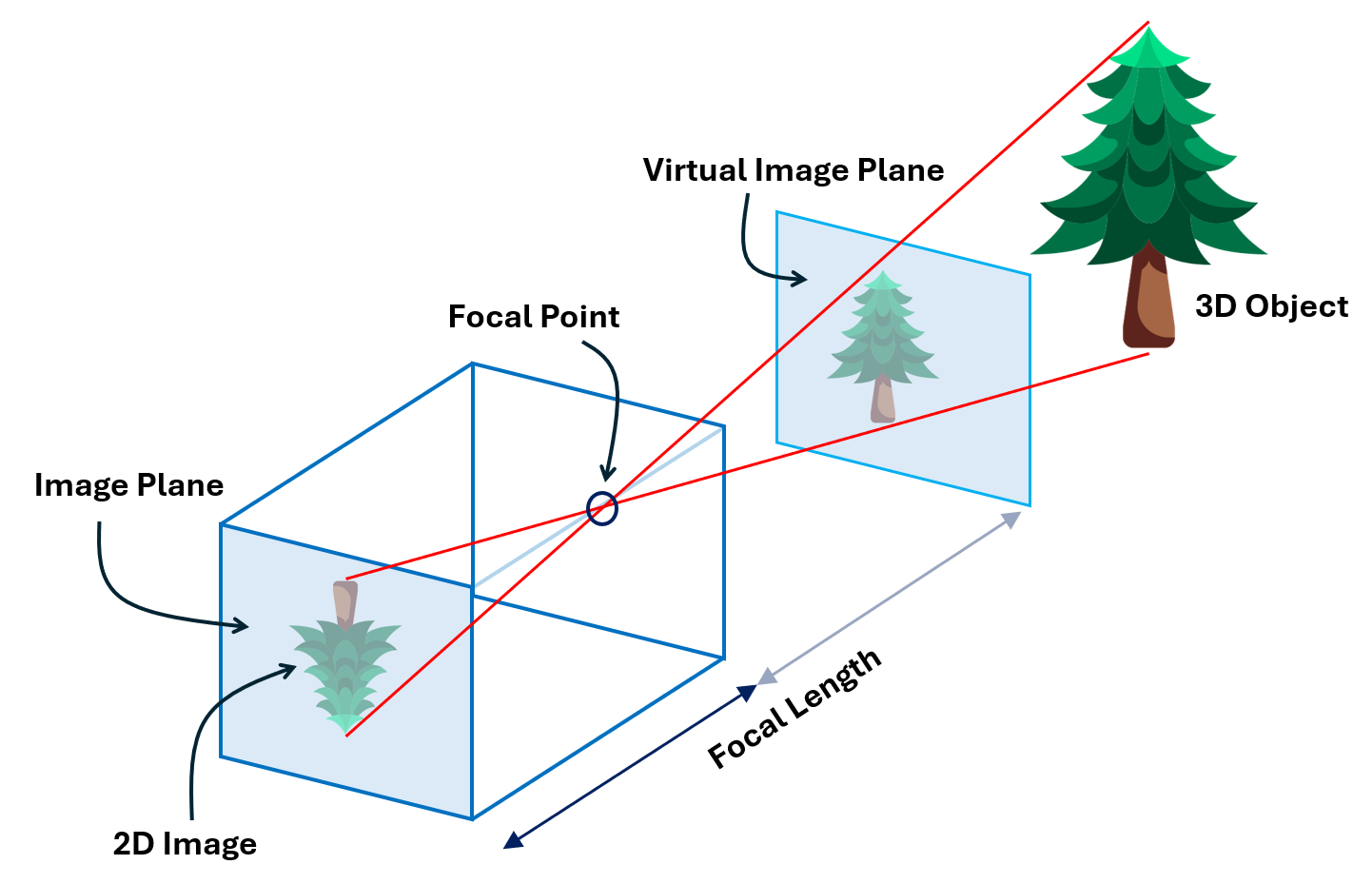
At its core, camera calibration models the camera as a mathematical system. A camera converts a 3‑D point X in the world into a 2‑D point x on the image plane according to

where, P is a camera matrix. This matrix encodes both intrinsic and extrinsic parameters. Calibration aims to identify the geometric characteristics of the image formation process.
Intrinsic parameters
Intrinsic parameters describe the internal optics and sensor geometry of a camera. They allow mapping between pixel coordinates and camera coordinates. Key intrinsics include:
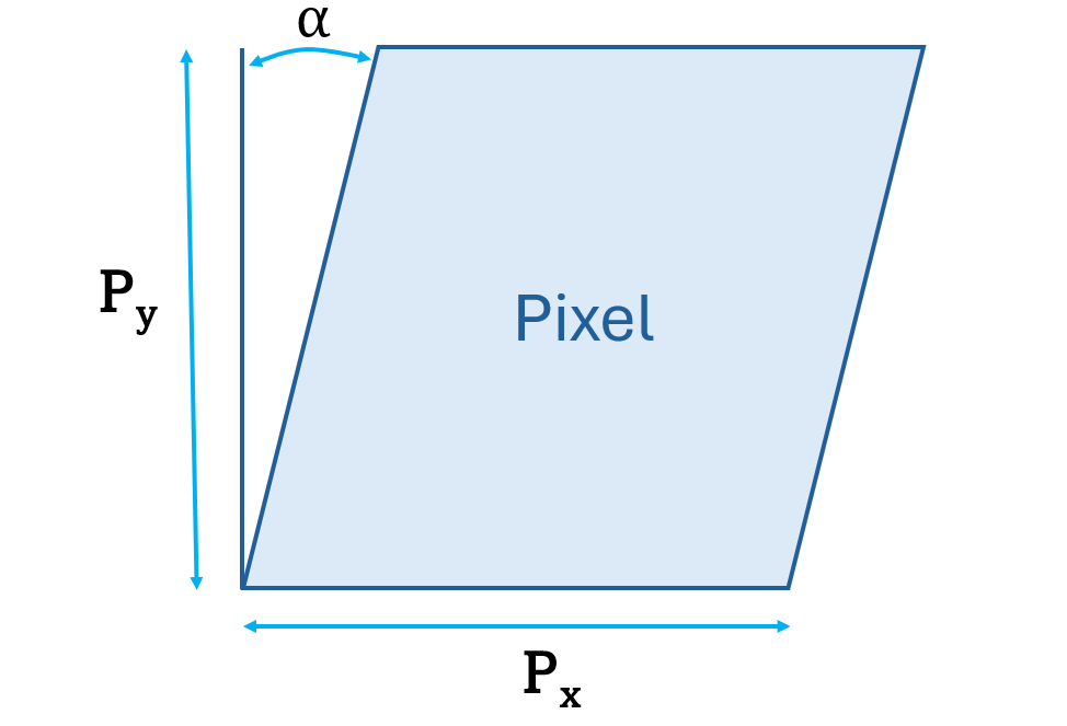
- Skew coefficient s: This checks if your camera's pixels form perfect rectangles or if they're slightly tilted. If skew is zero (which it almost always is in modern cameras), the pixels are perfectly rectangular and lined up straight. If it's not zero, the pixels are skewed or slanted.
- Principal point (cx,cy): The principal point is where the camera's optical axis intersects the image sensor. An incorrect principal point causes a systematic offset, everything in the captured image appears shifted horizontally or vertically from where it should be.
- Focal length f: Focal length defines how the camera projects 3D scenes onto the 2D sensor. An incorrect focal length causes objects to appear distorted, either stretched or compressed in size.
- Lens distortion coefficients: These are parameters such as k1, k2, k3 for radial distortion and p1, p2 for tangential distortion. These coefficients correct deviations introduced by the lens. Without compensation, straight lines appear curved, especially near the edges.
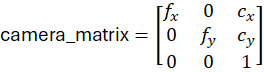
The intrinsic parameters are typically stored in a 3 x 3 camera matrix:
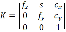
where fx and fy are focal lengths in pixels along the x and y axes. They define the magnification of the camera. The difference between fx and fy indicates non-square pixels (common in some sensors). The pixel skew is defined as:
Extrinsic parameters
Extrinsic parameters define the camera’s pose relative to a reference world coordinate system. They consist of:
- Translation vector t: It gives the camera’s position along the X, Y, Z axes. Miscalibrated translation leads to errors in distance measurement and perspective.
- Rotation matrix R: It describes how the camera is oriented with respect to the world axes. Incorrect orientation misaligns multi‑camera setups and 3‑D reconstruction.
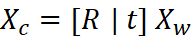
The extrinsic matrix [R | t] transforms 3‑D world coordinates Xw to camera coordinates Xc such that:
Combined projection
Combining the intrinsic matrix K and extrinsic matrix [R | t] gives the full camera projection matrix denoted by:
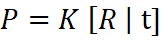
which maps world points to image points. Solving for K, R and t from observed correspondences is the essence of calibration.
Lens Distortion Effects
Real lenses do not behave like a perfect pinhole camera. When light passes through a lens, it bends in slightly uneven ways. This bending causes distortion, meaning the image does not match the true shape of objects in the real world. One of the main goals of camera calibration is to correct these distortions so the image becomes geometrically accurate.
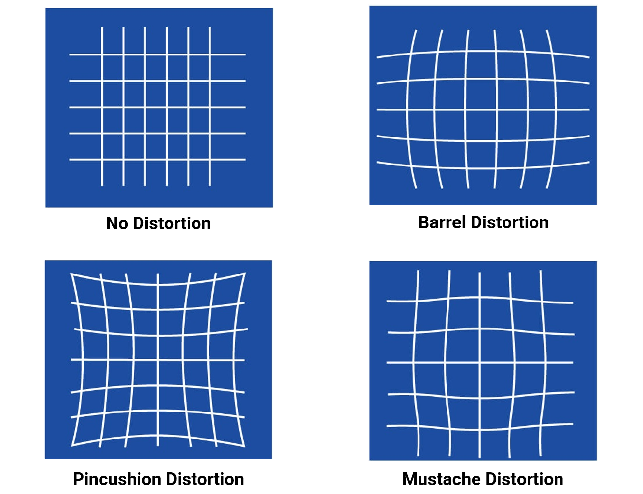
Radial Distortion
Radial distortion happens because the curved lens elements bend light more at the edges than at the center. This makes straight lines appear curved in the image, especially near the borders. It produces the common “bowing” effect seen in many lenses. There are three types of radial distortion:
Barrel Distortion
Barrel distortion is a type of radial distortion where image magnification decreases as you move away from the center. This makes lines bow outward, creating a barrel-like shape. It is often seen in wide-angle and fisheye lenses.
Pincushion Distortion
Pincushion distortion is the opposite effect. Here, image magnification increases toward the edges. Straight lines bend inward, like the shape of a pincushion. This distortion is common in telephoto lenses.
Mustache Distortion
Mustache distortion is a mix of barrel and pincushion distortion in the same image. Lines first curve outward, then inward, creating a wave-like or “mustache” shape. This type of distortion usually appears in complex zoom lenses.
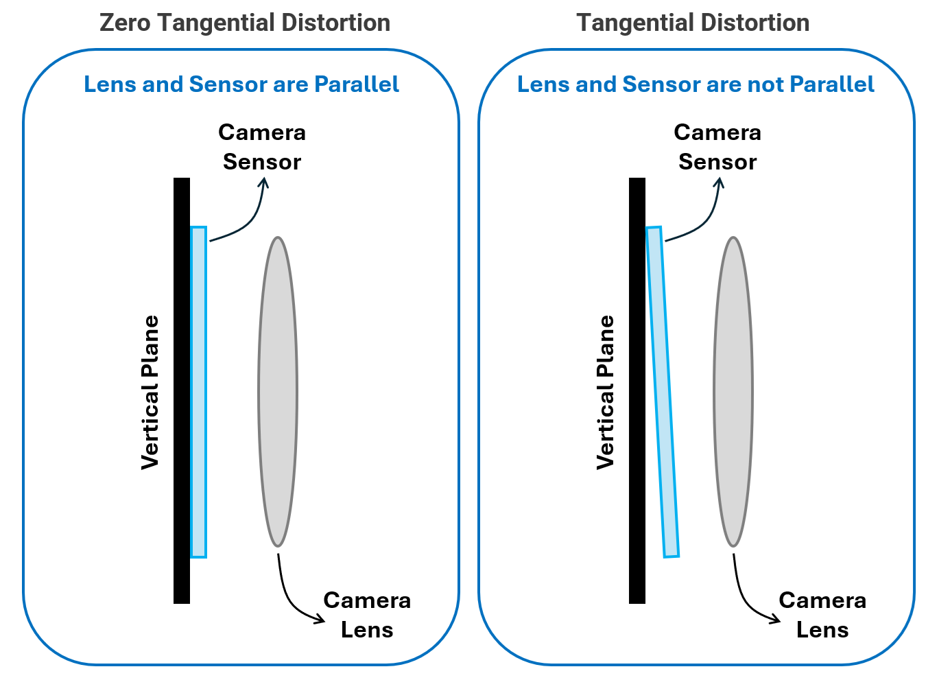
Tangential Distortion
Tangential distortion occurs when the lens is not perfectly aligned with the image sensor. If the lens is slightly tilted or shifted, the image appears slanted or stretched. Parts of the image may look closer or farther than expected.
Other Non-Geometric Effects
Some distortions are not geometric but still affect image quality.
Examples include:
- Vignetting: darkening at the corners of the image
- Chromatic aberration: color fringing caused by the lens focusing different wavelengths at slightly different points
Advanced calibration pipelines may estimate and correct these effects as well.
Types of Camera Calibration
Different applications use different camera setups, so the calibration method also changes. Whether you are calibrating a single camera, a stereo pair, or a full multi-camera system, the goal is the same: estimate the camera’s intrinsic parameters, distortion coefficients, and the geometric relationship between cameras. Below are the main types of camera calibration used in computer vision and robotics.
Single-Camera Calibration (Monocular)
This is the most common type of calibration. It estimates a camera’s intrinsic matrix and lens distortion coefficients using images of a known calibration target.
To perform this calibration, the camera observes a pattern usually a checkerboard, asymmetric circle grid, or Charuco board from different angles and positions. Algorithms such as Zhang’s method use the detected points on the pattern to match their known 3D positions with their 2D image coordinates. The method then solves for the camera parameters that minimize reprojection error, which measures the difference between predicted 2D points and actual detected points.
Checkerboards are widely used because their corners can be detected with sub-pixel accuracy, while circle grids and Charuco boards offer better robustness when parts of the pattern are occluded.
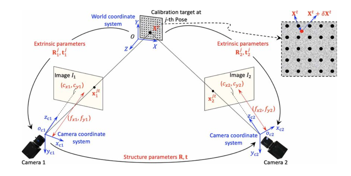
Stereo Camera Calibration
A stereo system uses two cameras to estimate depth. Calibration determines:
- Intrinsic parameters of each camera (focal length, principal point, distortion)
- Extrinsic parameters between them (rotation R and translation t from left to right camera)
Once intrinsic and extrinsic are known, the stereo pair understands how the same 3D point appears in both images. This allows the system to perform epipolar geometry, compute disparity, and ultimately estimate depth through triangulation. In simple terms, stereo calibration teaches the two cameras how they are arranged in space so they can accurately perceive 3D structure.
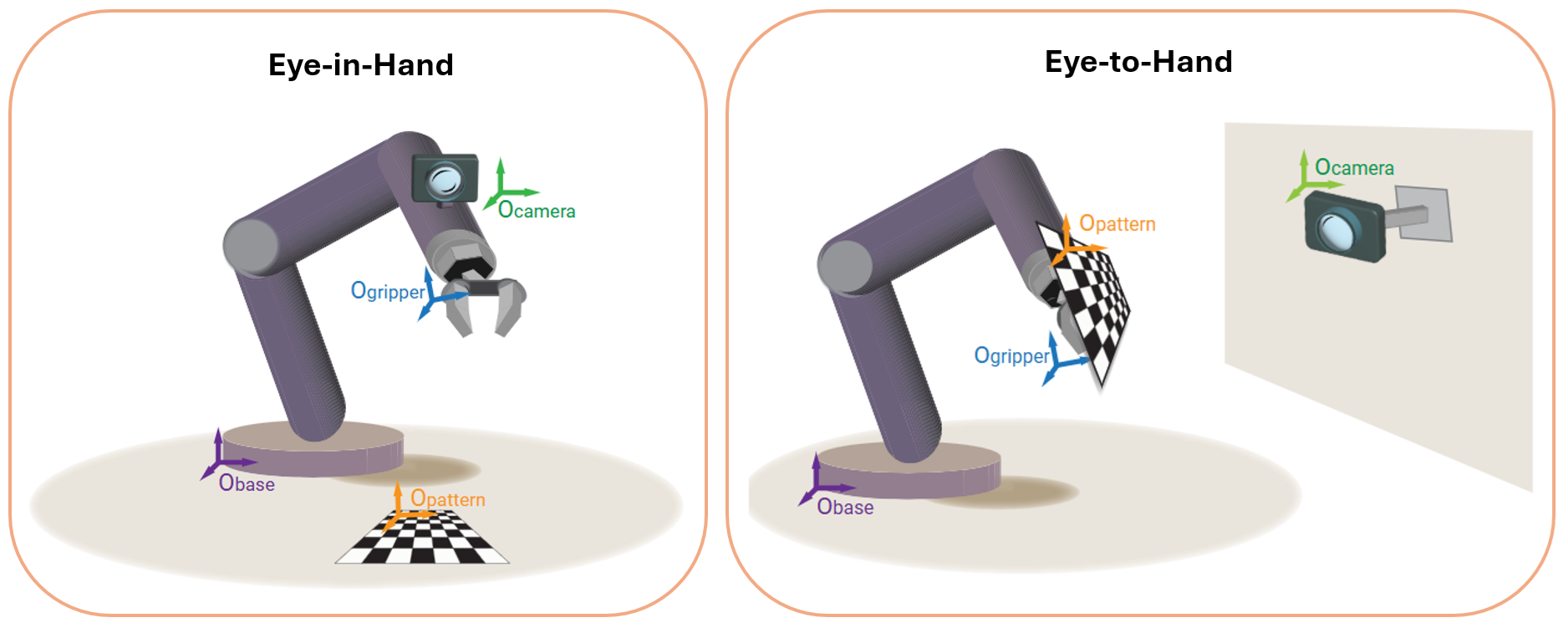
Robot Hand-Eye Calibration (Eye-in-Hand / Eye-to-Hand)
Hand-eye calibration determines the spatial relationship between a camera and a robot. This is essential when a camera is either mounted on the robot or observing the robot's workspace.
There are two setups:
- Eye-in-Hand: The camera is attached to the robot’s end-effector (gripper/tool). Calibration solves for TE→C, tthe fixed transformation from end-effector to camera.
- Eye-to-Hand: Camera is fixed in the environment, observing the robot. Calibration solves for TB→C, the transformation from robot base to camera.
The classic approach solves AX = XB, where:
- A = robot motion (transformation between two end-effector poses)
- B = corresponding motion observed by the camera (transformation between calibration target poses)
- X = the unknown hand-eye transformation
This calibration enables the robot to accurately relate camera observations to its own coordinate frame, enabling precise visual servoing and object manipulation.
Let's Explore a Camera Calibration Example
Calibrating a camera is a two-stage process: first you estimate the camera’s intrinsic and distortion parameters, and then you apply those parameters when processing images. OpenCV computes the intrinsic camera matrix (with zero skew, assuming rectangular pixels) and distortion coefficients using checkerboard images. Once these parameters are obtained, they can be reused to undistort every incoming frame. This section walks through the complete set of steps, from capturing calibration images to applying calibration inside Roboflow workflow for accurate, distortion-free inference.
Intrinsic matrix in OpenCV: skew is zero
The general camera intrinsic matrix in projective geometry is:
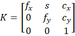
- fx, fy - focal lengths in pixel units
- cx, cy - principal point (optical center) in pixels
- s - skew term (shear between x and y axes)
In most practical cameras (and in OpenCV’s default model):
- pixels are assumed to be rectangular,
- x and y axes are assumed to be perpendicular (no shear).
So OpenCV sets the skew s = 0 and uses:
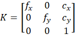
This is exactly what you see in the OpenCV docs. It define the camera matrix with zero skew. Therefore we will build the intrinsic matrix in our code (and to be used in Roboflow workflo), that uses only fx, fy , cx, cy.
Step-By-Step Camera Calibration Guide
The following steps show how to calibrate camera using OpenCV and use the parameter in Camera Calibration block in Roboflow Workflows.
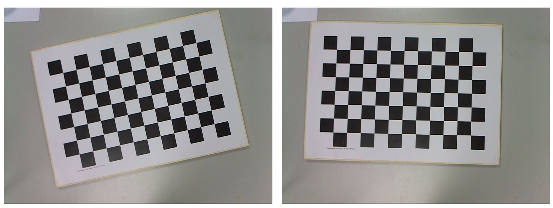
Step 1. Print a calibration pattern and capture images
Print a checkerboard (or use a monitor displaying one). Capture 10–20 images of the board:
- Different positions in the frame (center, corners, edges)
- Different orientations (tilt, rotation, distance)
- Good lighting, no motion blur
These images are the raw data for calibration.
Step 2. Define the checkerboard pattern and real-world geometry
We must tell OpenCV:
- How many inner corners (not squares) the board has
- The real size of one square (e.g., 30 mm)
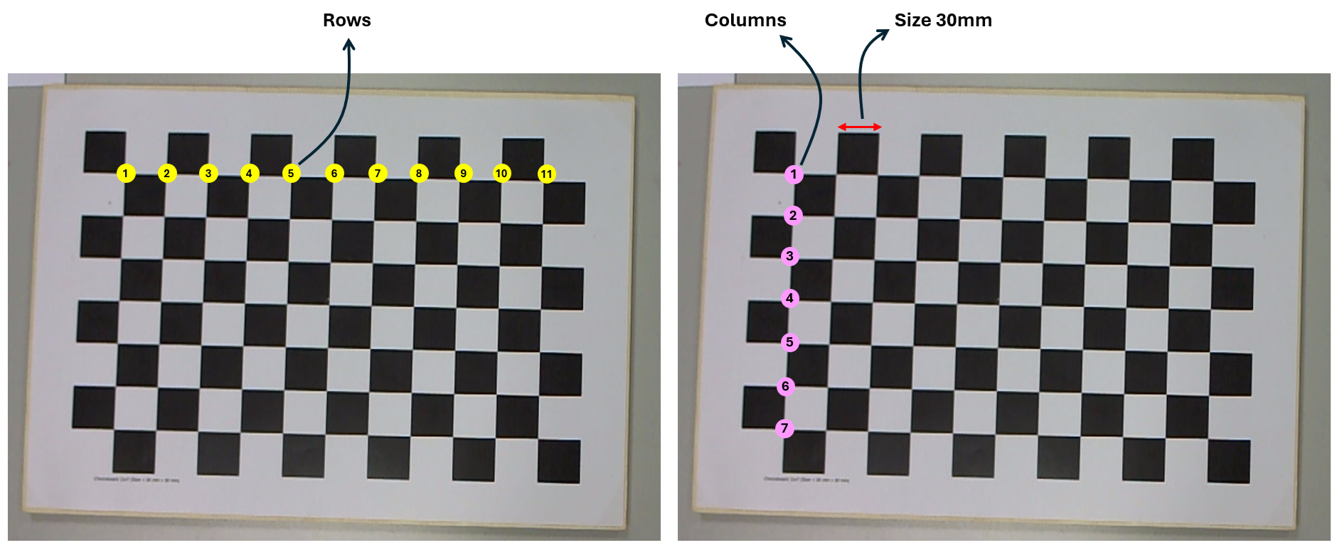
CHECKERBOARD = (11, 7)   # (columns, rows) of inner corners
SQUARE_SIZE = 0.030     # 30 mm
Now generate the 3D coordinates of each corner assuming the board lies in the Z=0 plane:
import numpy as np

objp = np.zeros((CHECKERBOARD[0] * CHECKERBOARD[1], 3), np.float32)
objp[:, :2] = np.mgrid[0:CHECKERBOARD[0],
                       0:CHECKERBOARD[1]].T.reshape(-1, 2)
objp *= SQUARE_SIZE
These are object points in world coordinates. For each calibration image, the board shape is identical, only the pose changes.
Step 3. Detect checkerboard corners in each image
Now perform following operation for each calibration image:
- Load the image and convert to grayscale.
- Detect corners with
cv2.findChessboardCorners(). - Refine to sub-pixel accuracy with
cv2.cornerSubPix(). - Store matched 3D/2D point sets:
objpoints,imgpoints.
import cv2
import glob

objpoints = []  # 3D points in world space
imgpoints = []  # 2D points in image plane

images = glob.glob("calib_images/*.jpg")

criteria = (cv2.TERM_CRITERIA_EPS + cv2.TERM_CRITERIA_MAX_ITER,
            30, 0.001)

for fname in images:
    img = cv2.imread(fname)
    gray = cv2.cvtColor(img, cv2.COLOR_BGR2GRAY)

    ret, corners = cv2.findChessboardCorners(gray, CHECKERBOARD, None)

    if ret:
        corners_refined = cv2.cornerSubPix(
            gray,
            corners,
            winSize=(11, 11),
            zeroZone=(-1, -1),
            criteria=criteria,
        )

        objpoints.append(objp)
        imgpoints.append(corners_refined)

        # Optional: visualize detection
        cv2.drawChessboardCorners(img, CHECKERBOARD, corners_refined, ret)
        cv2.imshow("img", img);
        cv2.waitKey(100)

cv2.destroyAllWindows()
Output will be similar to following:
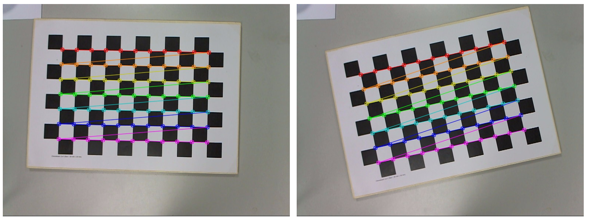
We now have 3D positions of board corners in objpoints[i] and 2D pixel positions of those corners in image i in imgpoints[i].
Step 4. Run camera calibration
To estimate intrinsics and distortion use OpenCV’s calibrateCamera()
ret, camera_matrix, dist_coeffs, rvecs, tvecs = cv2.calibrateCamera(
    objpoints,
    imgpoints,
    gray.shape[::-1],  # (width, height)
    None,
    None
)
This will outputs intrinsic matrix (fx, fy, cx, cy) with zero skew as camera_m atrix, distortion coefficients (usually [k1, k2, p1, p2, k3]) as ` dist_coeffs`, extrinsic parameters (pose of the board for each image) as rvecs, tvecs and average reprojection error (fit quality) as ret. You can inspect them using code below:
print("Camera matrix:\n", camera_matrix)
print("Distortion coefficients:\n", dist_coeffs.ravel())
print("Reprojection error:", ret)
This is the moment the camera is mathematically calibrated. The `camera_matrix` has the form:
The skew term is the off-diagonal entry in position (0,1). OpenCV sets this to 0, which encodes the assumption that:
- the x and y axes are orthogonal
- pixels are rectangular
- no shear between image axes
This simplifies the model and works for almost all modern cameras. You can extract the parameters:
fx = camera_matrix[0, 0]
fy = camera_matrix[1, 1]
cx = camera_matrix[0, 2]
cy = camera_matrix[1, 2]

dist = dist_coeffs.ravel()
k1, k2, p1, p2, k3 = dist[0:5]
These 9 values (fx, fy, cx, cy, k1, k2, k3, p1, p2) are exactly what the Roboflow Camera Calibration block expects. You can store these values optionally:
import json
calibration = {
    "fx": float(fx),
    "fy": float(fy),
    "cx": float(cx),
    "cy": float(cy),
    "k1": float(k1),
    "k2": float(k2),
    "k3": float(k3),
    "p1": float(p1),
    "p2": float(p2)
}
with open("camera_calibration.json", "w") as f:
    json.dump(calibration, f, indent=2)
Step 4. Use the parameters in the Roboflow Workflow
Once the intrinsic and distortion parameters have been estimated, the next step is to apply them inside a Roboflow Workflow so that every incoming image is automatically undistorted before model inference. This is done using the Camera Calibration block.
In the workflow, the setup is straightforward. The workflow starts with an Inputs block that receives an image/video. This image is passed directly into the Camera Calibration block. The block takes intrinsic parameters such as focal lengths (fx, fy), principal point (cx, cy), and distortion coefficients (k1, k2, k3, p1, p2). These are the same numbers produced by your calibration script. The block simply applies them to remove lens distortion.
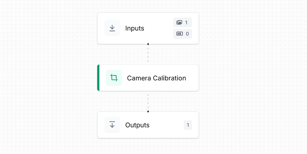
The calibration block reconstructs the camera matrix internally and undistorts the image using OpenCV’s undistort() function. You don’t need to run calibration again inside Roboflow. The block uses the values you already computed and applies the correction to every frame.
Finally, the corrected output image is mapped to the Outputs block. Any downstream model (object detection, classification, pose estimation, etc.) would now receive this clean, distortion-free image.
So this Workflow takes a raw input image, applies camera calibration using fx, fy, cx, cy and distortion parameters, and produces an undistorted image ready for inference - all done automatically.
Camera Calibration Conclusion
Camera calibration is important process for building reliable computer vision application. By understanding how a camera maps the 3D world onto a 2D sensor and correcting the distortions that naturally arise from lenses, geometry and sensor layout, we give vision AI models a truthful view of the scene. Calibrated images provide the stable, distortion-free foundation for computer vision systems for tasks like object detection, pose estimation, depth measurement or robotic navigation. Once the intrinsic and distortion parameters are estimated and applied in tools, every frame becomes a consistent, measurable image that downstream models can trust. Calibration is an essential part of any precise, real-world AI pipeline.
Cite this Post
Use the following entry to cite this post in your research:
Timothy M. (Dec 8, 2025). Vision AI Camera Calibration Guide. Roboflow Blog: https://blog.roboflow.com/vision-ai-camera-calibration/