

Hand-eye calibration measures the fixed transform between a robot's camera and its gripper (T_G_C), which is what lets you convert an object the camera sees into a position the robot can reach: P_B = T_B_G × T_G_C × P_C. Compute T_G_C once with a checkerboard and OpenCV's cv2.calibrateHandEye(), then in a Roboflow Workflow RF-DETR finds the target, depth turns the pixel into a 3D camera-frame point, and two matrix multiplies return robot-base coordinates ready for a grasp.
Hand-eye calibration is the process of measuring where a camera sits relative to a robot, so that a position the camera sees can be converted into a position the robot can move to.
There are two common setups. In eye-to-hand, the camera is mounted somewhere fixed in the workcell and watches the robot from outside, so calibration finds the transform between the camera and the robot base. In eye-in-hand, the camera is mounted on the arm near the gripper and moves with it, so calibration finds the transform between the camera and the gripper. This guide uses the eye-in-hand setup.
I use RF-DETR to find the target in each image the wrist camera captures. Then, the camera's depth data turns that detection into a 3D point in the camera's frame, and the calibrated transform, combined with the robot's current pose, maps it into robot-base coordinates. Everything after calibration runs inside a Roboflow Workflow, so the detection, depth conversion, and coordinate transforms live in one pipeline.
In this project, you will:
- Calculate the camera-to-gripper transform
- Detect the target with RF-DETR
- Estimate its 3D position relative to the camera
- Convert that position into robot-base coordinates
Let's get started.
What Hand-Eye Calibration Calculates
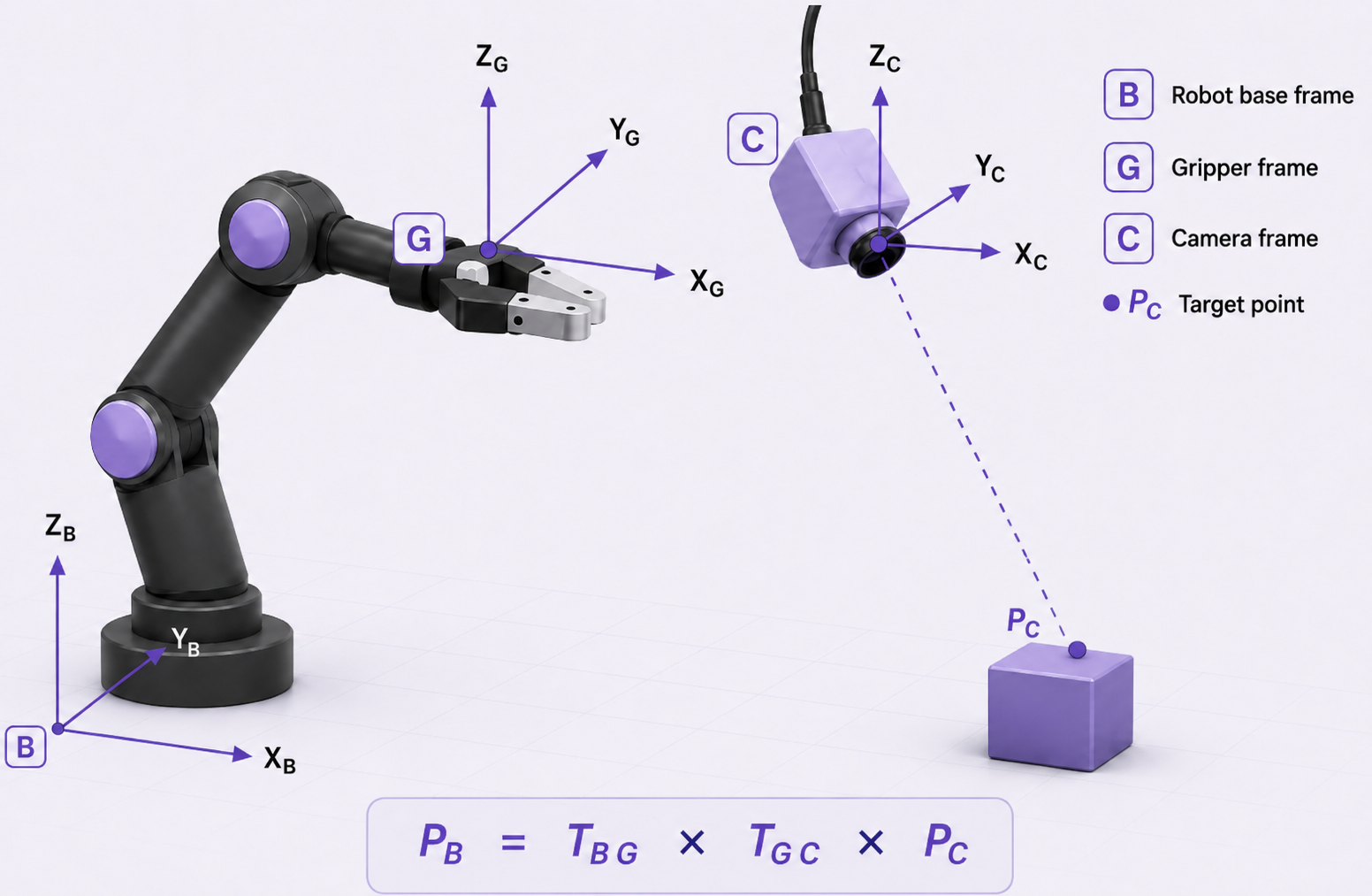
For this eye-in-hand setup, we use three reference frames: the camera frame C, the gripper frame G, and the robot base frame B. Each frame has its own X, Y, and Z axes for describing position and orientation.
The calibration result is the camera-to-gripper transform T_G_C, which describes how the camera is positioned relative to the gripper. It contains both translation and rotation. Translation gives the camera position along the gripper’s X, Y, and Z axes, while rotation describes the direction the camera is facing relative to the gripper.
RF-DETR gives us the target location in the image. Using that location with the camera’s depth data, we can estimate its 3D position relative to the camera, which we call P_C. We then use T_G_C together with T_B_G to express the target in the robot base frame:
P_B = T_B_G × T_G_C × P_C
Each term represents a different part of the setup:
- P_B is the target position after it has been converted to robot-base coordinates.
- P_C is the target position in camera coordinates.
- T_G_C is the fixed transform from the camera frame to the gripper frame.
- T_B_G is the current gripper pose relative to the robot base.
T_G_C stays the same as long as the camera remains fixed relative to the gripper. T_B_G changes whenever the robot moves to a new pose.
Calculate the Camera-to-Gripper Transform
Before building the runtime workflow, we need to calculate T_G_C.
Mount the camera near the gripper and keep the checkerboard fixed. Then move the robot through several positions and wrist angles.
For each robot position, save:
- The gripper position and orientation relative to the robot base.
- The checkerboard position and orientation relative to the camera.
Get the gripper position and orientation from the robot. For the checkerboard, detect its corners in the image and use OpenCV’s cv2.solvePnP() to calculate its position and orientation relative to the camera. In the code, each measurement is stored as a rotation matrix and a translation vector. Collect at least three measurement sets with different arm positions and wrist angles.
Pass these measurements to OpenCV's cv2.calibrateHandEye() to calculate the camera-to-gripper rotation and translation.
R_cam2gripper, t_cam2gripper = cv2.calibrateHandEye(
    R_gripper2base,
    t_gripper2base,
    R_target2cam,
    t_target2cam,
    method=cv2.CALIB_HAND_EYE_TSAI
)
Combine the returned rotation and translation into the 4 × 4 matrix:
T_G_C = np.eye(4)
T_G_C[:3, :3] = R_cam2gripper
T_G_C[:3, 3] = np.asarray(t_cam2gripper).reshape(3)
Save the resulting T_G_C. In the next step, we will pass this matrix into the Roboflow workflows along with the current robot pose.
Detect the Target with RF-DETR in Workflows
The runtime Workflow uses T_G_C as one of its inputs. The full Workflow is shown below before we look at the detection stage.
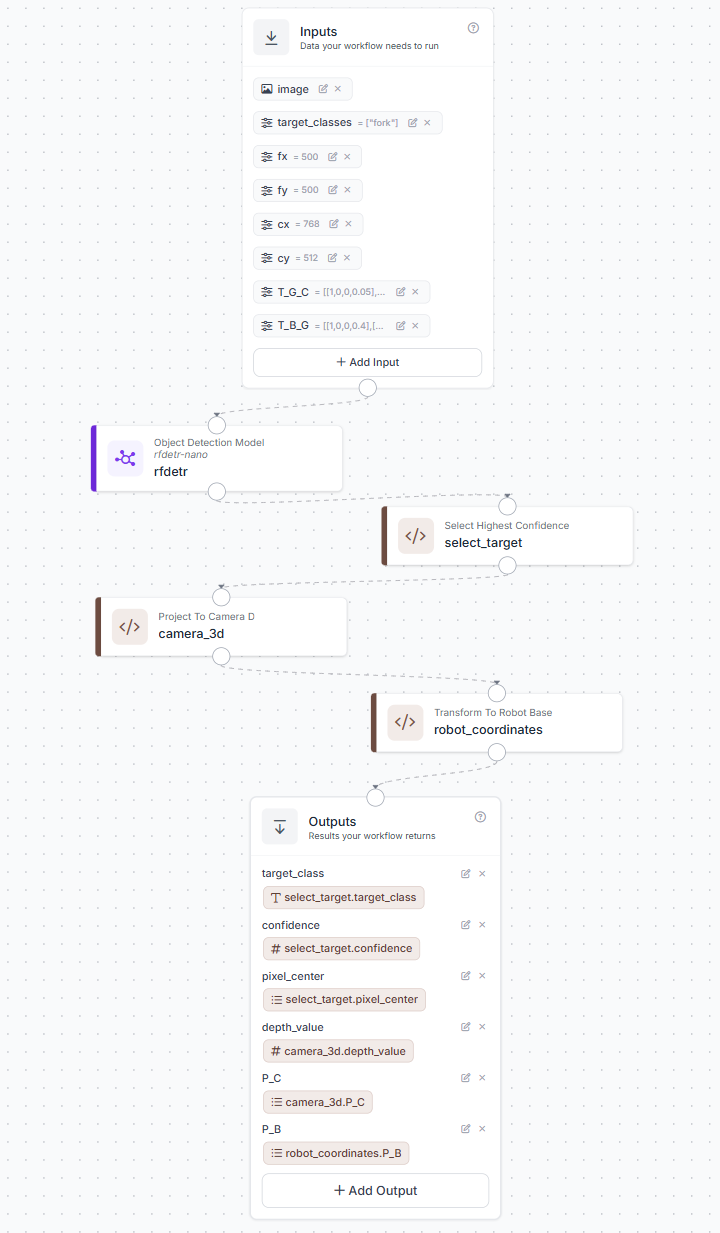
We will start with the detection stage. Add an Image Input followed by an Object Detection Model block. For this example, the model is RF-DETR Nano and the target class is set to fork.
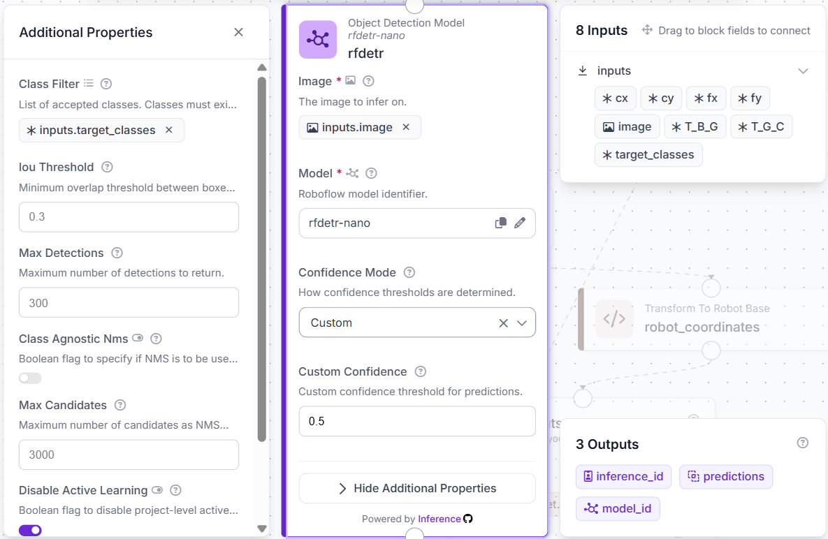
The Select Highest Confidence Custom Python block checks the RF-DETR predictions and keeps the detection with the highest confidence score.
def run(self, predictions):
    if len(predictions) == 0:
        return {
            'target_found': False,
            'target_class': '',
            'confidence': 0.0,
            'pixel_center': []
        }

    conf = predictions.confidence
    i = int(np.argmax(conf)) if conf is not None else 0

    box = predictions.xyxy[i]
    names = list(predictions.data.get('class_name', []))

    return {
        'target_found': True,
        'target_class': str(names[i]) if i < len(names) else '',
        'confidence': (
            round(float(conf[i]), 3)
            if conf is not None
            else 0.0
        ),
        'pixel_center': [
            float((box[0] + box[2]) / 2),
            float((box[1] + box[3]) / 2)
        ]
    }
We use this center point as (u, v), where u is the horizontal pixel coordinate, and v is the vertical pixel coordinate.
At this point, the Workflow has the target location in image coordinates. The next block takes (u, v) and converts it into a 3D camera-space position.
Convert the Detection into Robot Coordinates
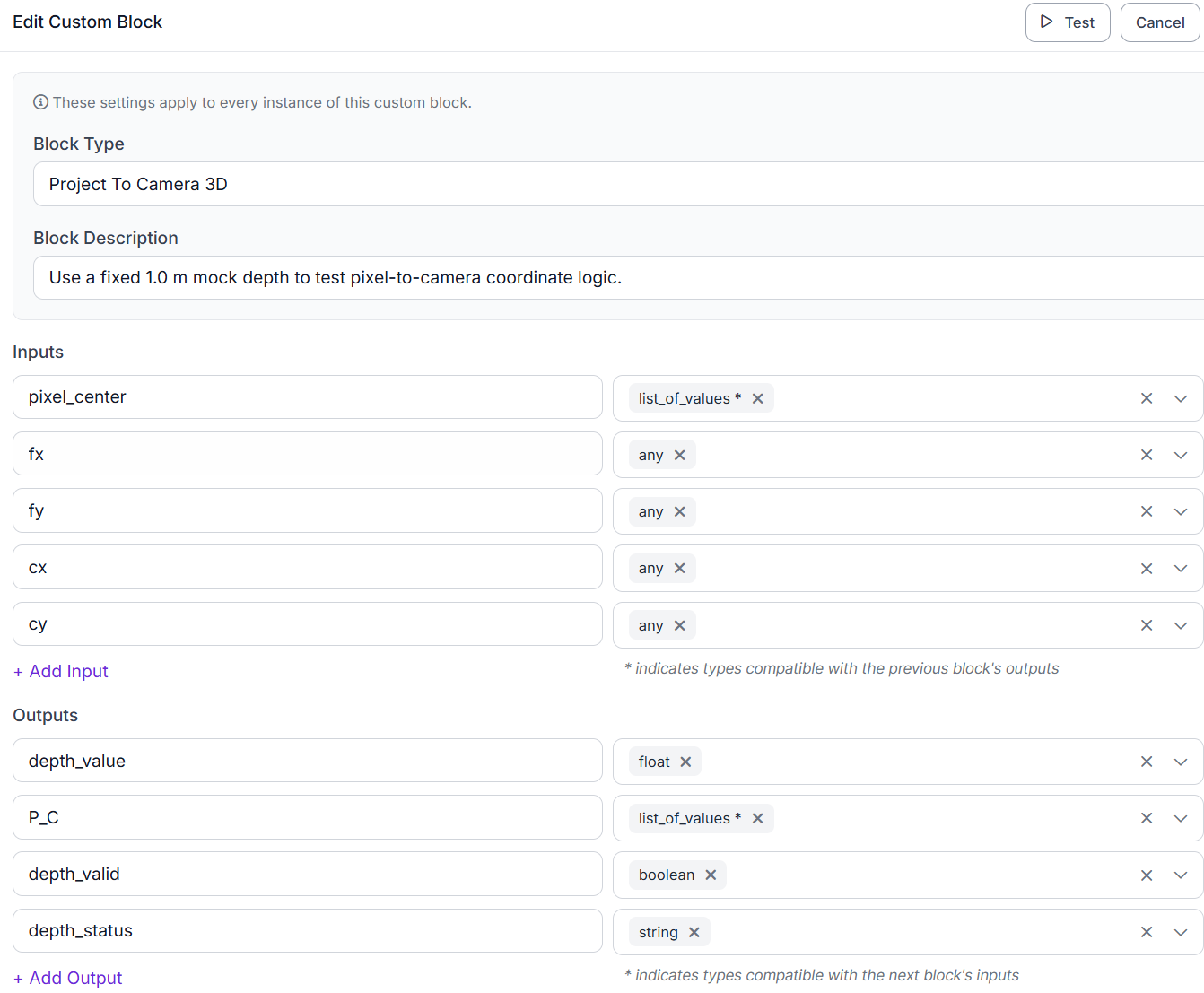
In a real setup, the depth at (u, v) would come from an RGB-D camera. For this test, we set it to 1.0 meter instead.
def run(self, pixel_center, fx, fy, cx, cy):
    if len(pixel_center) != 2:
        return {
            'depth_value': 0.0,
            'P_C': [],
            'depth_valid': False,
            'depth_status': 'No selected target.'
        }

    try:
        u, v = map(float, pixel_center)
        fx, fy, cx, cy = map(float, [fx, fy, cx, cy])

        if fx == 0 or fy == 0:
            raise ValueError('fx and fy must be nonzero.')

        z = 1.0

        return {
            'depth_value': z,
            'P_C': [(u-cx)*z/fx, (v-cy)*z/fy, z, 1.0],
            'depth_valid': True,
            'depth_status': 'mock depth'
        }

    except Exception as e:
        return {
            'depth_value': 0.0,
            'P_C': [],
            'depth_valid': False,
            'depth_status': str(e)
        }
The block returns P_C, which is passed to the next block. The final 1.0 lets the point be multiplied by the 4 × 4 transform matrices.
The matrices used in this test are simple fixed values. On hardware, T_G_C would come from the hand-eye calibration and T_B_G would come from the robot's current gripper pose. The Transform To Robot Base block takes P_C, T_G_C, and T_B_G and calculates the target position in robot-base coordinates.
def run(self, P_C, T_G_C, T_B_G):
    def fail(msg):
        return {
            'P_G': [],
            'P_B': [],
            'robot_base_position': [],
            'transform_valid': False,
            'transform_status': msg
        }

    try:
        if len(P_C) != 4:
            return fail(
                'P_C is unavailable because depth conversion failed.'
            )

        def a(x):
            return np.asarray(
                json.loads(x) if isinstance(x, str) else x,
                dtype=float
            )

        pc = np.asarray(P_C, float)
        pg = a(T_G_C).reshape(4, 4) @ pc
        pb = a(T_B_G).reshape(4, 4) @ pg

        return {
            'P_G': pg.tolist(),
            'P_B': np.round(pb, 3).tolist(),
            'robot_base_position': np.round(pb[:3], 3).tolist(),
            'transform_valid': True,
            'transform_status': 'ok'
        }

    except Exception as e:
        return fail(str(e))
The block returns P_B, the target position in robot-base coordinates, as part of the Workflow output.
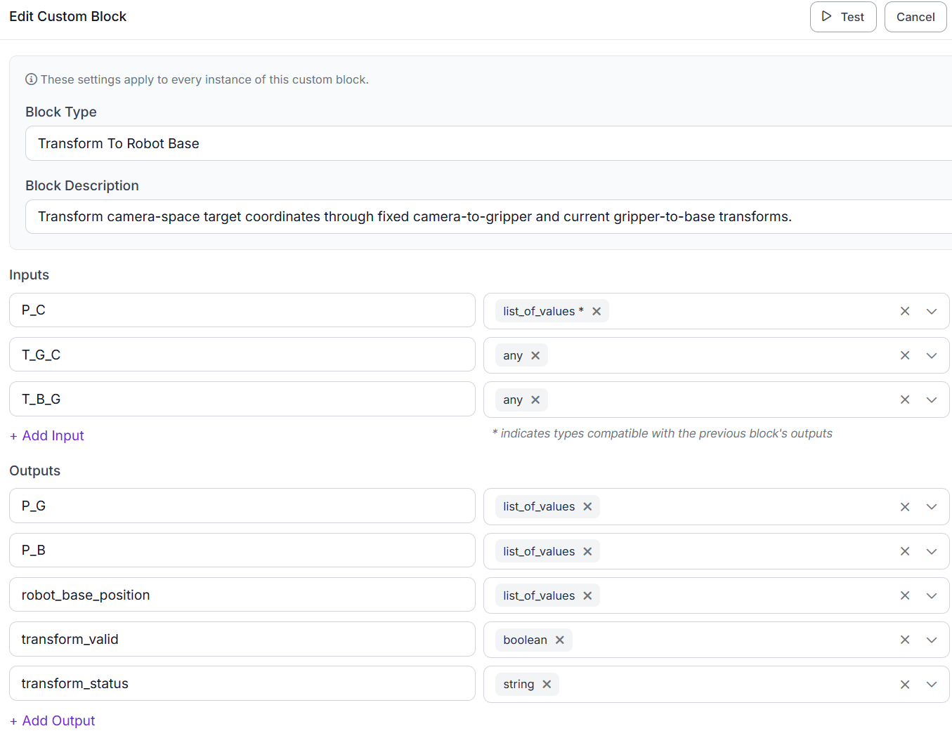
For this example, the center of the RF-DETR bounding box is used as the target point. A real picking system may instead use a point chosen specifically for where the gripper should contact the object.
Test the Complete Hand-Eye Calibration Workflow
The RF-DETR detection in this run is real. The camera values and transforms are fixed test inputs, so we use the result to check the Workflow calculations.
Run the test image through the Workflow. First, confirm that RF-DETR detects the correct object. Then check that pixel_center matches the selected detection and review the returned P_C and P_B values.
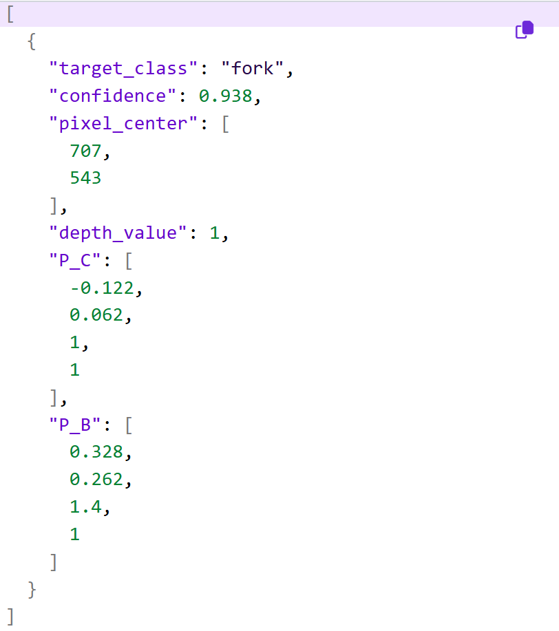
To measure accuracy on a real robot, replace the mock depth with the depth from the RGB-D camera, then compare the returned P_B with known robot-base coordinates. Test the target at several positions and wrist angles to see whether the error stays consistent or changes with the robot pose.
When to Recalibrate or Update the Model
Recalculate T_G_C whenever the physical setup between the camera and gripper changes. If the camera is moved or rotated, calibrate again. The same applies if the camera is remounted or the gripper reference frame changes.
Update or retrain RF-DETR when the visual task changes. Retrain it if the robot needs to detect a new object class or if it repeatedly misses objects it should recognize.
Changing RF-DETR does not require a new hand-eye calibration if the camera mount has not changed. If the camera moves, RF-DETR may still detect the object correctly while P_B is wrong because the saved T_G_C no longer matches the camera position.
Conclusion
This project connects RF-DETR detection with hand-eye calibration to return a target position in robot-base coordinates. The Workflow uses the detected target to calculate P_C. Then it combines P_C with T_G_C and the current robot pose to return P_B.
For the test shown here, depth is fixed at 1.0 meter, so the result only verifies that the Workflow calculations are working as expected. In a deployed setup, that value would come from an RGB-D camera. With real depth and calibrated camera values, P_B can be passed to the robot for tasks such as approaching, picking, or grasp planning.
Further Reading:


Cite this Post
Use the following entry to cite this post in your research:
Mostafa Ibrahim. (Aug 10, 2026). Hand-Eye Calibration for Robot Vision with RF-DETR. Roboflow Blog: https://blog.roboflow.com/hand-eye-calibration/