

You can turn a production line camera into a real-time inspection system by training an RF-DETR detection model, connecting it to a Roboflow Workflow, and running inference at the edge on Roboflow's AI1 Camera. This guide builds a complete bottle inspection pipeline that tracks and counts products, flags bottles missing a cap or label with a model that hit 99.9% mAP@50, and logs every defect as a Vision Event operators can act on.
Walk into any modern factory, and you will see cameras monitoring different stages of the production process. However, most cameras are only collecting footage. They can show what happened, but they cannot understand what is happening, detect issues, or help operators make decisions in real time.
What if a single camera could detect defects, count products, identify anomalies, and trigger actions the moment something goes wrong?
This is where production line monitoring with Camera AI comes in. Roboflow’s AI1 Camera allows manufacturers to transform live camera feeds into intelligent vision systems by combining cameras, computer vision models, and automated workflows. Instead of relying on manual inspections or reviewing footage after an issue occurs, AI1 enables teams to monitor production lines and respond to events as they happen.
In this article, we will explore how production line monitoring with Camera AI works, the problems it can solve in manufacturing, and how to build a similar system using Roboflow’s vision platform. We will cover the complete workflow, from collecting data and training a custom model with RF-DETR to creating automated logic with Roboflow Workflows and turning detections into actionable alerts. As an example, we'll build a bottle inspection system that detects bottles moving along a conveyor belt, counts production output, and identifies bottles that are missing a cap, label, or both.
What Is Production Line Monitoring with Camera AI?
In a manufacturing environment, every second matters. A production line can contain thousands of products moving through different stages, making it difficult for human operators to continuously monitor every detail. Production line monitoring with camera AI uses computer vision to analyze live camera feeds and automatically identify important events as they happen.
Instead of simply recording a video, an AI-powered camera system can understand what it sees. It can detect products, identify defects, track production activity, and turn visual information into structured events that teams can use to make decisions.
At a high level, every production monitoring system follows three main steps:
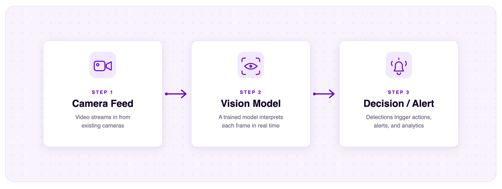
1. Camera Feed
The process starts with a camera capturing live footage from the production line. This could be a conveyor belt carrying products, an assembly station where parts are installed, or a workspace where safety conditions need to be monitored.
With Roboflow's AI1 Camera, manufacturers get an all-in-one vision system that combines the camera, computing hardware, lighting, and Roboflow's computer vision platform into a single device. This allows production lines to capture and process visual information without needing to build a separate camera and computing setup.
2. Vision Model
Once the camera captures an image or video frame, a computer vision model analyzes the information and identifies what is happening.
Depending on the application, the model can:
- Detect products moving through a production line
- Identify defects or missing components
- Verify correct assembly
- Count products and measure throughput
- Monitor safety requirements
AI1 supports running modern computer vision models, including models such as RF-DETR, directly as part of a production vision workflow. This enables manufacturers to use custom-trained models that are designed for their specific inspection needs.
3. Decision and Alert
Detecting an object is only the first step. A production monitoring system becomes valuable when detections are converted into actions.
For example:
- A defective product is detected → trigger an alert
- A missing component is identified → stop the line
- Product counts fall below the expected rate → notify an operator
With Roboflow Workflows, teams can connect models, logic, and integrations together to create automated vision pipelines. These workflows can transform raw camera detections into meaningful events that production systems can respond to.
The key advantage of AI-powered production monitoring is that it moves factories from passive video recording to active intelligence. Instead of discovering problems after production is complete, AI systems like AI1 can identify events as they happen and help teams respond immediately.
What Can Production Line Monitoring with Camera AI Monitor?
Production line monitoring with Camera AI can automate much more than quality inspections. By continuously analyzing live camera feeds, manufacturers can monitor production, verify assembly processes, identify safety issues, and collect production metrics in real time. Below are some of the most common manufacturing applications.
Defect Detection
Defect detection is one of the most common applications of production line monitoring. Instead of manually inspecting products after they leave the production line, computer vision models can inspect every product as it passes the camera and immediately identify issues such as missing components, damaged packaging, incorrect labels, or surface defects.
For example, a camera positioned above a bottling line could detect bottles missing a cap or label and automatically flag them for removal before they continue through production. Later in this article, we'll build a production monitoring system that uses this approach to inspect bottles moving along a conveyor belt using Roboflow AI1, RF-DETR, and Roboflow Workflows. Catching defects earlier helps improve product yield while reducing waste and costly rework.
Assembly Verification
Many manufacturing processes involve multiple assembly steps, and a single missing component can make an entire product unusable. Camera AI can verify that every required part has been installed correctly before a product moves to the next station.
For example, a vision system could confirm that all required components have been installed on an electronic assembly. Automating these checks helps improve first-pass yield while reducing assembly errors.
Throughput and Cycle-Time Monitoring
Production monitoring is about more than finding defects. By detecting and tracking products as they move through a production line, computer vision can automatically measure throughput, count completed products, and calculate cycle times.
These insights allow manufacturers to monitor production targets, identify bottlenecks, and improve Overall Equipment Effectiveness (OEE) without requiring manual counting or reporting.
Missed-Step Detection
Some manufacturing defects occur because a product skips an important stage in the production process. Camera AI can monitor each stage of the line and verify that required steps have been completed before a product continues.
For example, the system can confirm that a bottle has passed through the labeling station or that a package has been sealed before moving to shipping. Detecting missed steps early helps reduce rework and prevents incomplete products from reaching customers.
Safety and PPE Monitoring
Production monitoring systems can also improve workplace safety. Computer vision models can continuously monitor workers to verify that required personal protective equipment (PPE), such as helmets and safety vests, is being worn. They can also detect when personnel enter restricted areas or hazardous zones.
By identifying safety violations in real time, manufacturers can respond more quickly while improving compliance with workplace safety requirements.
How It Works: From Camera Feed to Automated Decision
A production monitoring system is more than just placing a camera above a conveyor belt. Behind every AI-powered inspection system is a pipeline that takes raw video from the production line, analyzes what is happening, and turns those observations into useful decisions.
The process starts with a live camera feed, where images from the production line are captured and passed through a computer vision model. The model identifies objects and features in each frame, and additional logic is used to determine whether those detections represent a normal product or an issue that requires attention.
Capturing Production Data with an AI Camera
The first step in any vision system is collecting visual information from the manufacturing environment. A camera continuously streams video as products move through different stages of production, providing a real-time view of the production line.
Traditional industrial cameras are often used only for recording footage. While this can be useful for reviewing issues after they occur, it does not help operators identify problems as they happen.
An AI-powered camera changes this by combining image capture with computer vision capabilities. Instead of simply recording video, the system continuously analyzes the production line while products are moving through it.
Roboflow AI1 Camera combines the camera, computing hardware, and vision platform into a single system designed for real-world production environments. This allows manufacturers to capture, process, and analyze visual information without needing to build a separate camera setup and computing infrastructure.
Analyzing Frames with Computer Vision Models
As the video stream is processed, the computer vision model analyzes each frame and identifies objects based on what it has been trained to recognize.
For example, a model monitoring a bottling line could detect bottles, caps, and labels as they move along a conveyor belt. In other applications, the model could identify defects, verify assembly steps, or monitor whether safety equipment is being used correctly.
Models such as RF-DETR allow manufacturers to train custom object detection models for their specific production requirements. Instead of using a generic model, teams can create systems designed around the exact products, components, and defects they need to monitor.
However, object detection is only the first step. A model can identify that a bottle, cap, and label are present, but it does not automatically determine whether that bottle passes inspection.
For example, the model may detect:
- Bottle
- Cap
- Label
The system still needs additional logic to determine whether those detections belong to the same bottle and whether the product meets the required quality standards.
Turning Detections into Decisions with Custom Logic
This is where custom logic becomes important. After the vision model produces detections, the system can apply rules based on the requirements of the production process.
For a bottle inspection system, this logic could check whether a detected bottle contains all required components. If a bottle contains both a cap and a label, it can be marked as a pass. If either component is missing, the system can classify it as defective and trigger an alert.
This additional layer allows computer vision systems to move beyond simple object detection and become complete inspection solutions.
Roboflow Workflows makes it possible to connect different parts of a vision pipeline, including detection models, tracking, custom Python logic, and integrations. This allows teams to create automated inspection systems that transform camera detections into meaningful production events.
Edge vs. Cloud Inference
Another important thing to consider when designing a production monitoring system is deciding where AI inference takes place. Computer vision models can either run directly on hardware near the camera, known as edge inference, or be processed remotely using cloud inference.
With edge inference, the AI model runs locally on a device near the production line. This reduces the amount of data that needs to be sent elsewhere, minimizes latency, and allows decisions to be made in real time.
This is the approach used by Roboflow AI1 Camera. By performing inference directly on the device, AI1 can inspect products, detect defects, and generate events without relying on a constant connection to the cloud. This makes it well suited for manufacturing applications where fast response times and reliable operation are important.
Cloud inference can also be useful, particularly when manufacturers need centralized monitoring across multiple facilities, want to manage models remotely, or require additional computing resources. However, sending images to remote servers can introduce additional latency depending on network conditions.
The right approach depends on the application. Systems that require immediate responses, such as quality inspection or safety monitoring, often benefit from edge inference, while cloud inference can be advantageous for large-scale analytics and centralized management.
By combining edge AI, computer vision models, and automated workflows, production monitoring systems can transform traditional cameras into intelligent tools that help manufacturers detect issues and make decisions in real time.
Building the Production Line Bottle Inspection System
For this tutorial, we will build a production line monitoring system that detects and tracks bottles moving along a conveyor belt, counts products as they pass through an inspection area, and automatically identifies bottles with missing components.
In a real manufacturing environment, this system would run using a camera positioned above the production line. Roboflow AI1 Camera allows manufacturers to connect live production footage with computer vision workflows, enabling products to be analyzed as they move through the factory.
In this tutorial, we will use a custom object detection model trained with Roboflow RF-DETR to detect bottles, caps, and tags (also known as labels). These detections will then be connected to a Roboflow Workflow that tracks products, counts bottles passing through an inspection point, and applies custom logic to determine whether each bottle passes quality control.
The completed Workflow will:
- Detect bottles, caps, and tags in real time
- Track bottles as they move through the production line
- Count bottles crossing a defined inspection area
- Identify bottles missing caps or tags
- Generate quality-control events for defective products
By the end of this tutorial, we will have built a complete computer vision pipeline that transforms a camera feed into an automated inspection system.
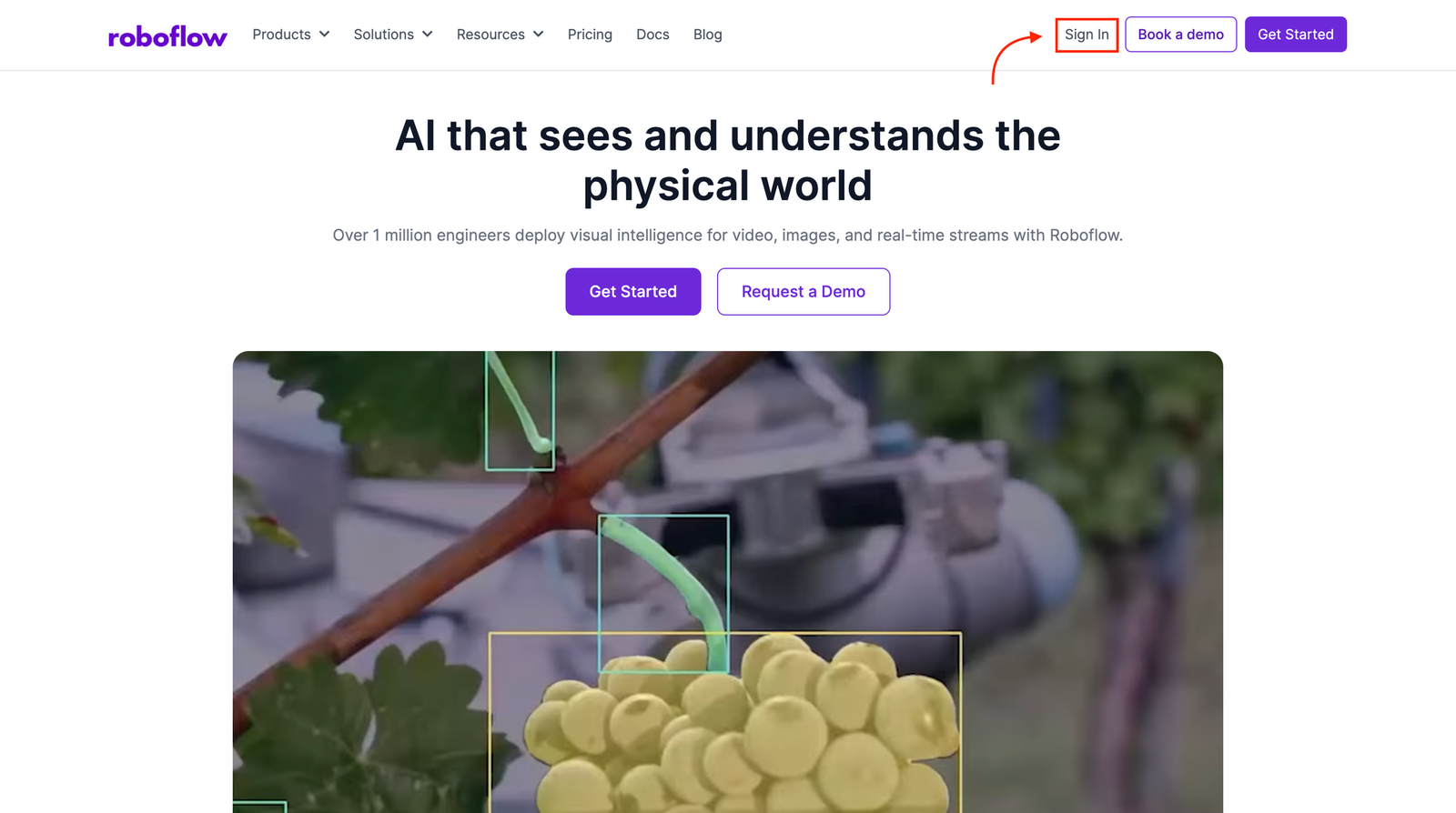
Step 1: Log in to Roboflow
Sign in to your Roboflow account and create a workspace if you do not already have one. The workspace will store the dataset, trained model, and Workflow used throughout this project.
Step 2: Fork the Bottle Detection Dataset
Collecting and annotating manufacturing data from scratch can be time-consuming. For this project, we will use an existing bottle detection dataset from Roboflow Universe.
The dataset contains images annotated for three object classes:
- Bottle
- Cap
- Tag
These classes allow the model to understand the different components required for inspection. The bottle class identifies products moving through the conveyor, while the cap and tag classes are used later to determine whether each bottle passes quality control.
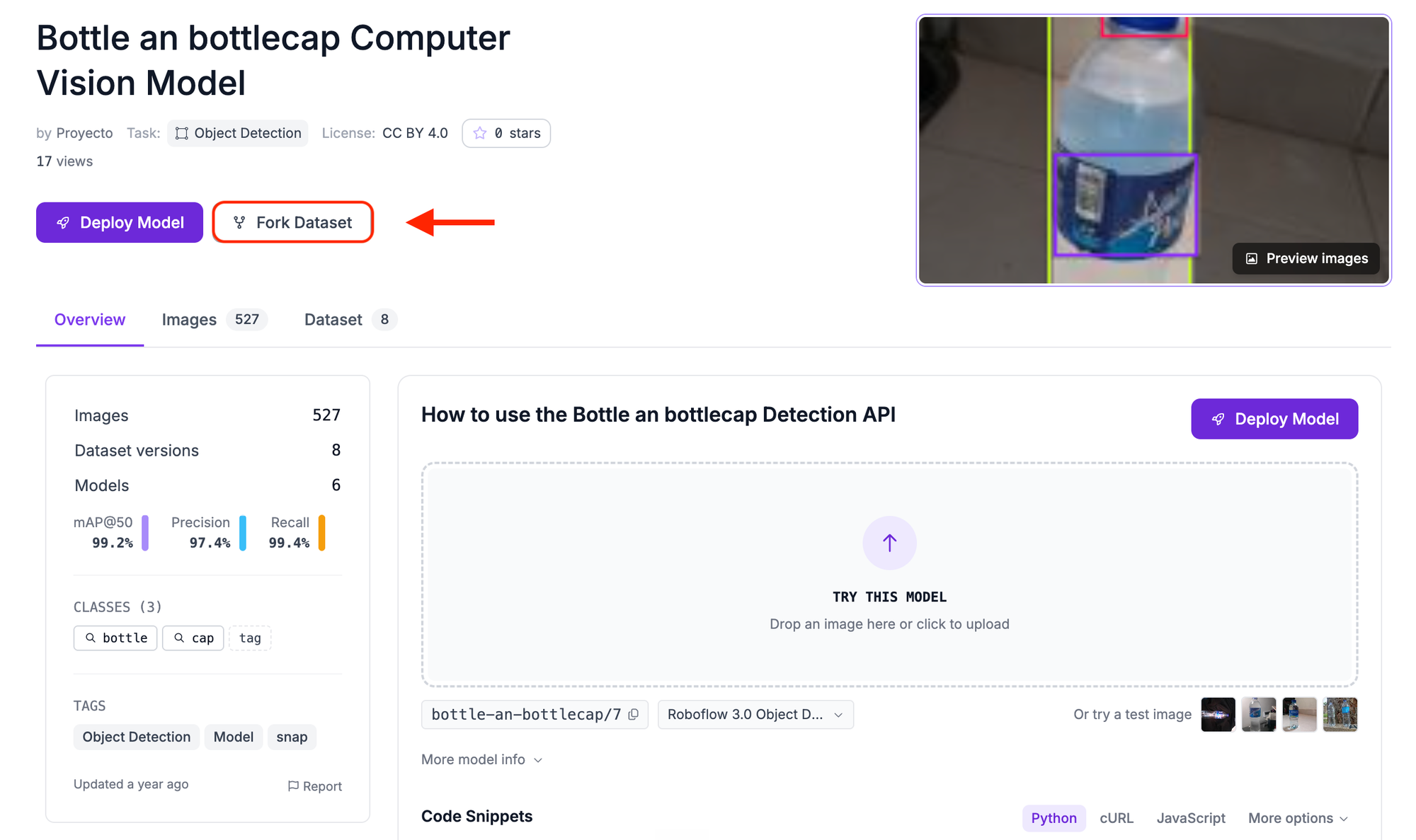
Open the dataset in Roboflow Universe and click Fork Dataset. Select your workspace and create a copy of the dataset by clicking Fork Dataset once again.
Forking the dataset allows you to generate your own dataset version and apply preprocessing and augmentation settings without modifying the original project.
Step 3: Train an RF-DETR Object Detection Model
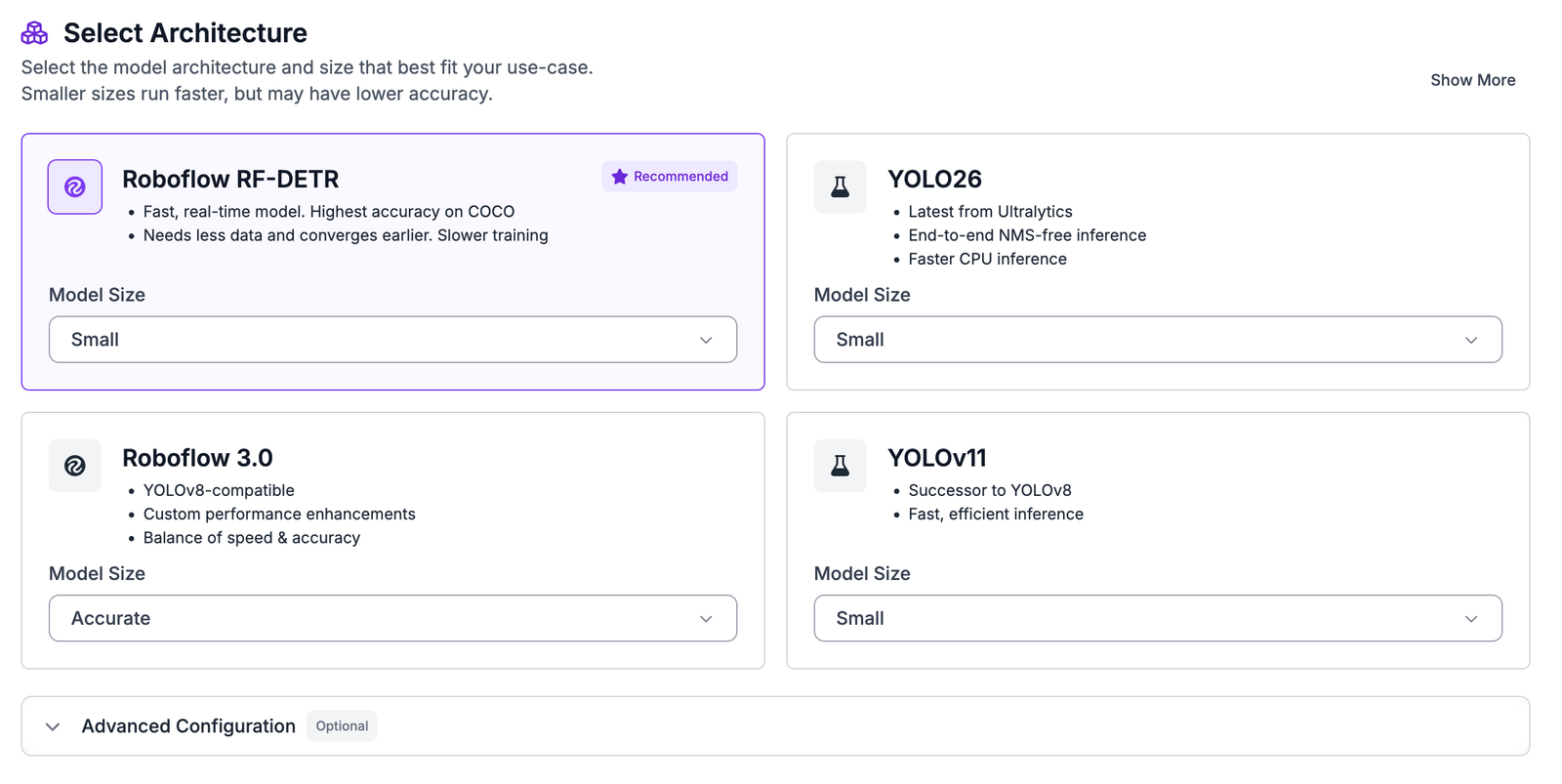
After forking the dataset, open the project and click the Train button.
Choose Custom Training and select RF-DETR Small as the model architecture.
RF-DETR is an object detection model that predicts the location and class of objects within an image. For this project, the model will learn to identify:
- Bottles moving through the production line
- Bottle caps
- Product labels
The model outputs the bounding box coordinates, class name, and confidence score for every detected object. These predictions will later be used by the Workflow to track bottles and perform quality checks.
Step 4: Configure the Dataset Version
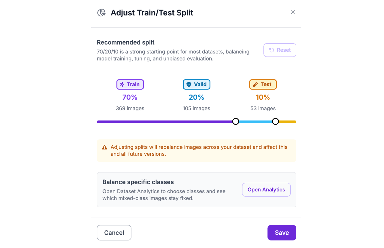
Before training begins, generate a dataset version by configuring the dataset split, preprocessing, and augmentation settings.
The dataset is divided into three groups: Training set, Validation set, Testing set
A common split is:
- 70% training
- 20% validation
- 10% testing
Roboflow automatically creates these splits when generating the dataset version.
Step 5: Apply Preprocessing and Augmentation
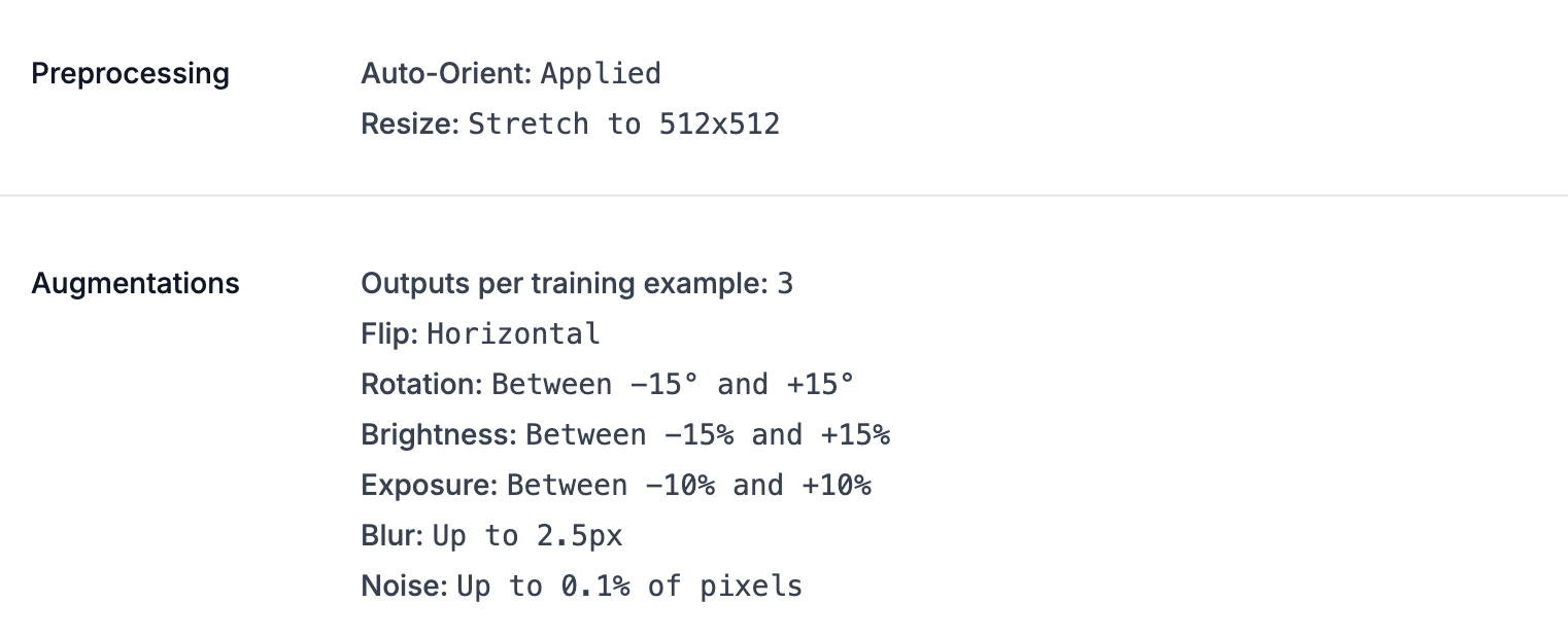
To help the model learn from different production conditions, preprocessing and augmentation can be applied during dataset generation.
Preprocessing creates a consistent format for every image, while augmentation introduces realistic variations that improve model generalization.
For preprocessing, apply:
- Auto-Orient: Automatically corrects image orientation using stored metadata.
- Resize: Resize images to 512 × 512 pixels so every image has the same input dimensions during training.
For augmentation, configure the outputs per training example to 3.
Apply these augmentations:
- Horizontal Flip: Helps the model recognize bottles when products appear in different horizontal orientations.
- Rotation (-15° to +15°): Simulates small camera alignment changes that may occur in a production environment.
- Brightness (-15% to +15%): Improves robustness to lighting variations.
- Exposure (-10% to +10%): Helps account for differences in camera exposure settings.
- Blur (up to 2.5px): Simulates slight motion blur caused by moving products.
- Noise (up to 0.1% of pixels): Introduces small image variations to improve generalization.
After configuring these settings, click Generate to create the dataset version.
Step 6: Evaluate the Trained Model
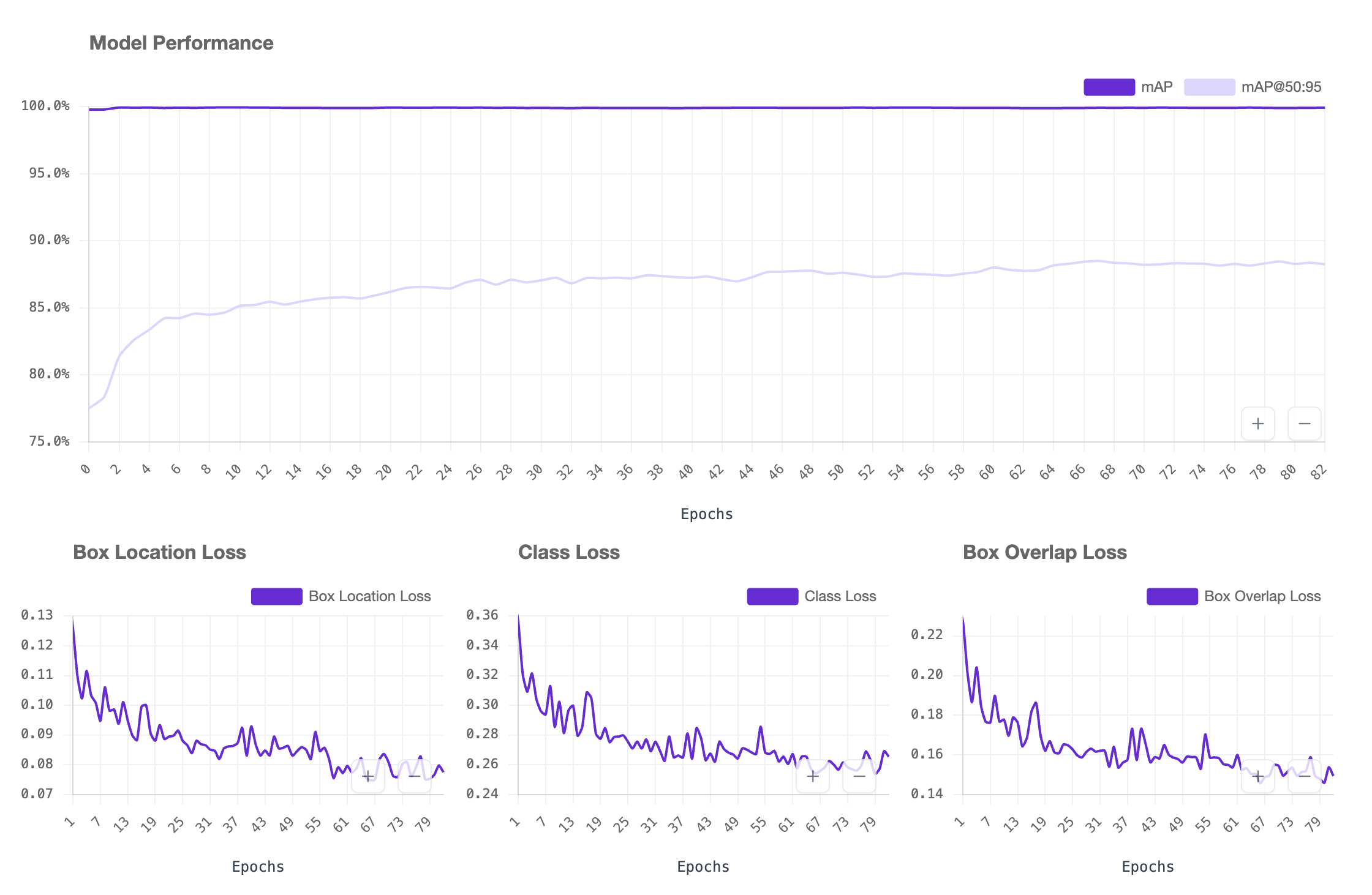
After training is complete, Roboflow evaluates the model using images from the testing set. These images are separate from the data used during training, allowing the model’s performance to be measured on examples it has not previously seen.
The trained bottle detection model achieved the following results:
| Metric | Score |
|---|---|
| mAP@50 | 99.9% |
| Precision | 99.4% |
| Recall | 100% |
| F1 Score | 99.7% |
The model achieved an mAP@50 of 99.9%, showing that it was able to accurately locate and classify bottles, caps, and tags across the test images. The precision score of 99.4% indicates that the model’s detections were highly reliable, with very few false detections. A recall score of 100% means the model successfully identified all annotated objects within the test set.
The F1 score of 99.7% shows that the model maintained a strong balance between precision and recall, making it suitable for the next stage of the workflow where detections are used for tracking, counting, and quality inspection.
While these results demonstrate strong performance on the testing images, real-world deployment should still include validation using footage from the actual production environment. Factors such as different lighting conditions, camera angles, bottle designs, conveyor speeds, and product variations can affect performance. Collecting additional images from the final setup and monitoring results after deployment can help ensure consistent performance.
Step 7: Build the Water Bottle Production Line Monitoring Workflow
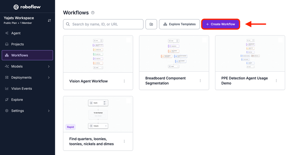
With a trained model in hand, it's time to build the production monitoring pipeline using Roboflow Workflows. Navigate to the Workflows tab in your Roboflow dashboard and click Create Workflow, then choose to start with a blank Workflow.
The Input and Output blocks are added automatically, so there's no need to create them yourself. The Input block includes an image field, which is what the Workflow uses to receive images or video frames. In a production deployment, this input would receive live frames from the AI1 Camera, but during development it allows you to test the Workflow using uploaded images or videos.
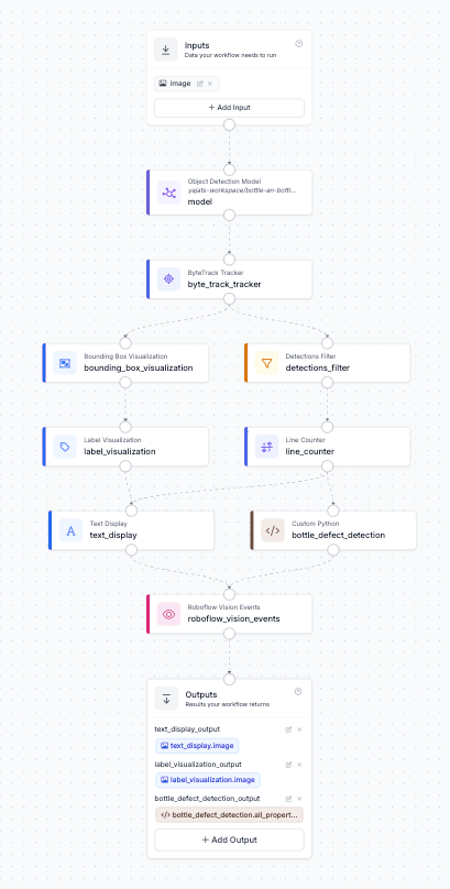
Before diving into each block, it's worth looking at the overall structure of the Workflow. Detection and tracking happen once at the beginning, and everything downstream branches off that single stream of tracked detections. One branch is responsible for the visual output, drawing bounding boxes, labels, and the bottle count on the video. The other branch performs the production logic, counting bottles as they cross the inspection line and determining whether each bottle passes quality inspection. The two branches come together at the end, allowing the Workflow to produce an annotated video while simultaneously logging quality-control events for defective bottles. You can explore the complete Workflow used in this tutorial here.
Block 1: Object Detection Model
This is the block that actually runs your trained RF-DETR model against each incoming frame. Click Add Block, search for Object Detection Model, and connect its image input to the workflow's Inputs block. In the Model field, select the bottle detection model you trained in Step 3, and set Confidence Mode to Best (Recommended) so the block automatically picks sensible thresholds per class instead of you tuning one number for bottles, caps, and tags all at once.

This block outputs predictions, which is every bottle, cap, and tag detected in the frame, along with an inference_id and model_id that get passed downstream. Everything else in the workflow builds on top of this single set of detections.
Block 2: ByteTrack Tracker
Detecting objects frame by frame isn't enough on its own, since the same bottle would get counted over and over as it moves across dozens of frames. Add a ByteTrack Tracker block and connect its detections input to the model's predictions output. This block assigns a persistent ID to each object so the workflow knows it's looking at the same bottle from one frame to the next, rather than treating every detection as brand new.
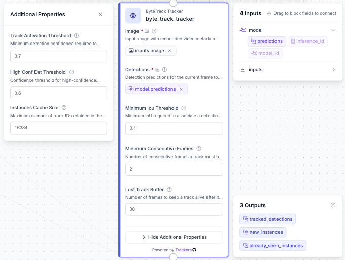
Byte Track includes several configuration options that control how detections are associated across frames, but for this workflow we use the default settings. These defaults are designed to maintain stable object identities while handling normal variations such as small movements or brief occlusions. The output from this block, tracked_detections, contains the detections with assigned tracker IDs and becomes the foundation for the downstream counting and quality-control logic.
Building the Visualization Branch
From the tracker, one branch exists purely to draw what's happening onscreen. This is what eventually becomes your annotated output video, but on its own it has no idea whether a bottle passed or failed inspection.
Block 3: Bounding Box Visualization
Add a Bounding Box Visualization block and connect its predictions input to the tracker's tracked_detections. This draws a box around every tracked object, bottles, caps, and tags alike, directly onto the input image.

At this stage it's just boxes with no labels, which is fine, since the next block is what makes those boxes actually legible.
Block 4: Label Visualization
Add a Label Visualization block, connect its input image to the bounding box block's output, and connect its predictions to the tracker's tracked_detections again. Set the Text field to Class so each box gets tagged with what it actually is.
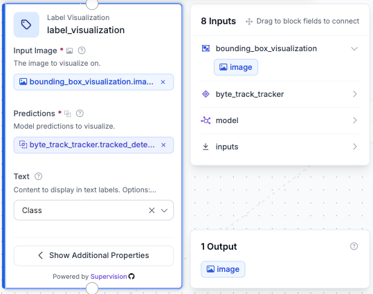
Now every bottle, cap, and tag on screen is boxed and labeled, which makes the output genuinely useful for a human glancing at a monitor on the factory floor, not just for the logic running behind it.
Building the Counting and Inspection Branch
The second branch coming off the tracker doesn't touch the video at all. Its job is purely numerical, deciding which bottle to inspect and when.
Block 5: Detections Filter
Add a Detections Filter block and connect it to the tracker's tracked_detections. Set Filter By to Class & Confidence, check Object Class, and enter bottle as the only included class.
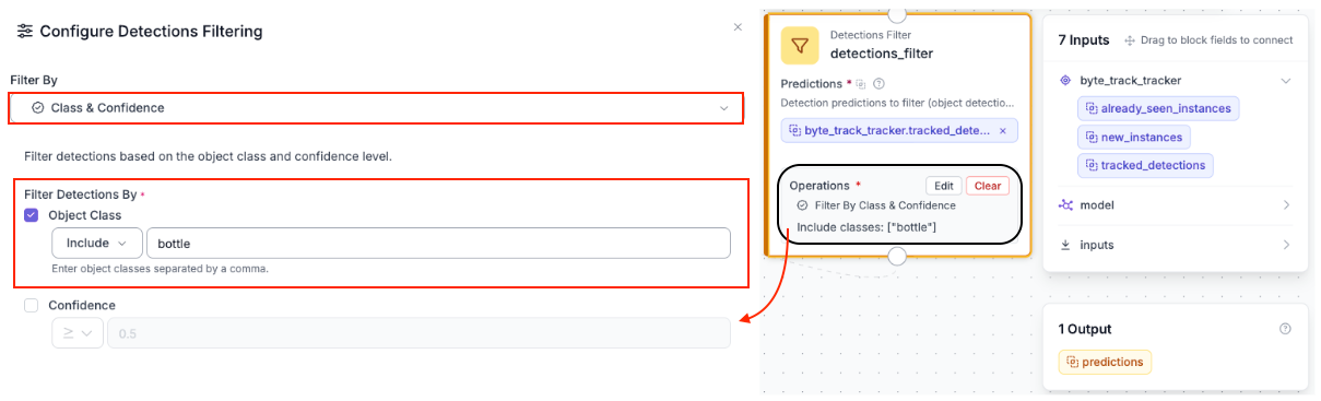
This matters because caps and tags are also tracked objects at this point, and if they were left in, the line counter downstream would count every cap and tag crossing the line right alongside the bottles. Filtering down to just the bottle class means the next block only ever sees the objects it should actually be counting.
Block 6: Line Counter
Add a Line Counter block and connect its detections input to the filtered predictions from the previous step. Click Set Line and draw a line segment across the point on the frame where a bottle should be considered fully inspected, in this case the coordinates [[152,708],[150,15]], which cuts across the conveyor belt near the start of the inspection area.
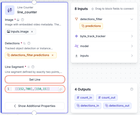
This works like a virtual tripwire. Every time a tracked bottle crosses that line, it gets logged as a crossing, and the block outputs both a running count_out and the specific detections_out for whichever bottle just crossed. That crossing is the trigger for everything that happens next, since it's the moment the workflow decides a bottle is ready to be judged pass or fail.
Block 7: Text Display
This is where the two branches start to come back together. Add a Text Display block, set its input image to the label visualization block's output, and set the Text field to Bottle Count: {{ $parameters.bottle_count }}. In Text Parameters, map bottle_count to $steps.line_counter.count_out.
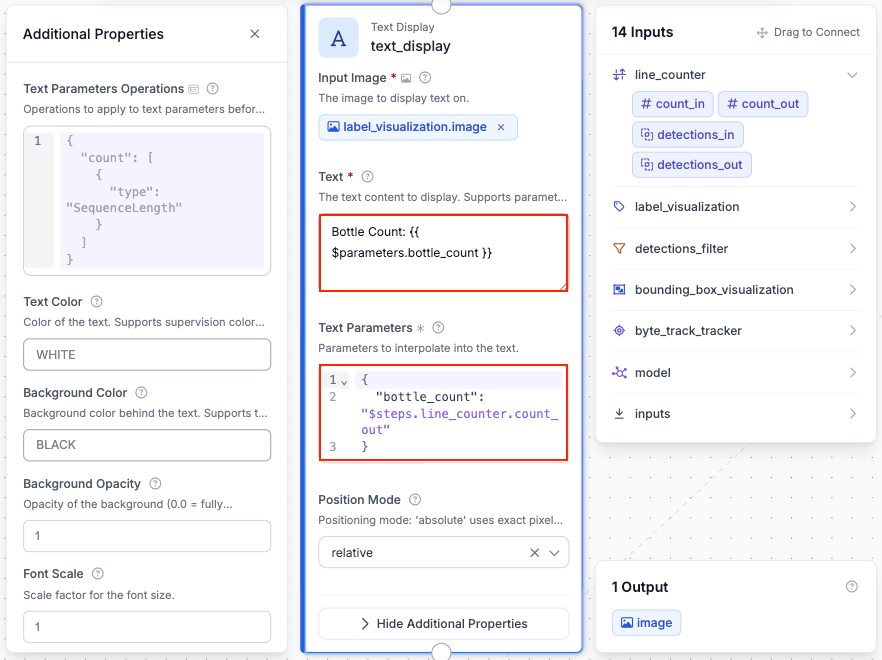
That double-curly-brace syntax is how Workflows lets you drop a dynamic value into a static string, so instead of a hardcoded label, the overlay updates in real time as bottles cross the line. This is also the block that finally merges the visualization branch, which supplies the labeled image, with the counting branch, which supplies the number itself.
Block 8: Custom Python (bottle_defect_detection)
Detecting a bottle, a cap, and a tag separately is not the same as knowing whether a specific bottle actually has its cap and tag on it. That association has to be computed, which is what this block does.
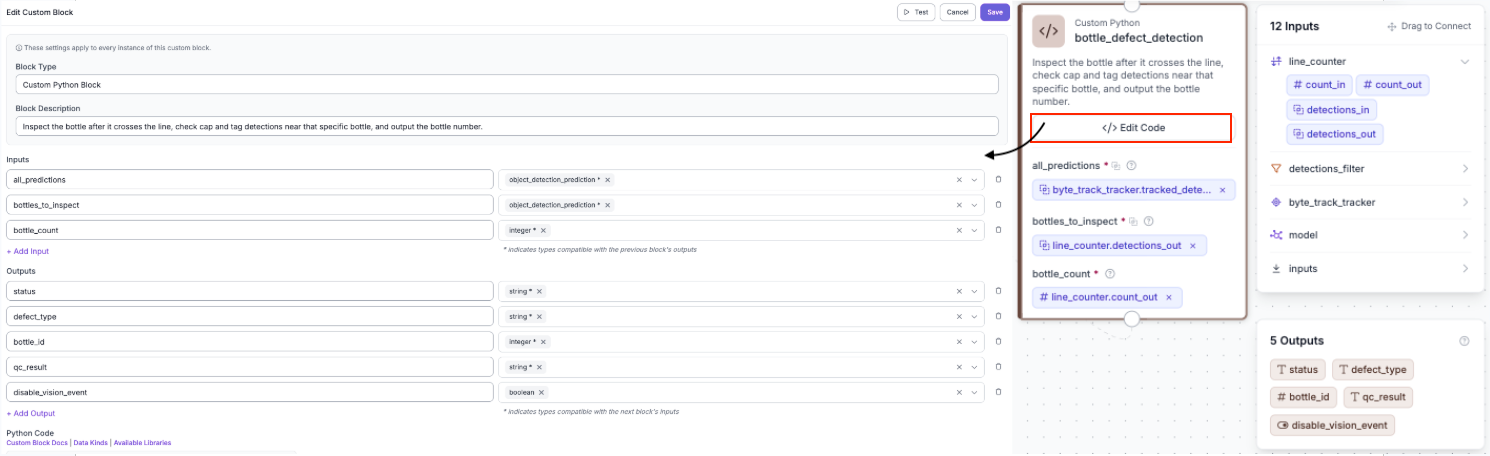
Add a Custom Python Block and name it bottle_defect_detection. Under Inputs, add three fields: all_predictions as type object_detection_prediction, connected to the tracker's tracked_detections, bottles_to_inspect as type object_detection_prediction, connected to the line counter's detections_out, and bottle_count as type integer, connected to the line counter's count_out.
Under Outputs, add five fields to match what the function returns: status as string, defect_type as string, bottle_id as integer, qc_result as string, and disable_vision_event as boolean. These five map directly onto the dictionary keys returned by make_result in the code below, so the names need to match exactly or the downstream blocks won't be able to find them. Click Edit Code to write the inspection logic and input the following information.
def run(self, all_predictions, bottles_to_inspect, bottle_count):
    if not hasattr(self, "alerted_tracker_ids"):
        self.alerted_tracker_ids = set()
    try:
        bottle_id = int(bottle_count)
    except (TypeError, ValueError):
        bottle_id = 0

    def make_result(status, defect_type, tracker_key=None):
        is_defect = status == "FAIL"
        should_send_event = is_defect
        # Prevent duplicate Vision Events for the same tracked bottle.
        if is_defect and tracker_key is not None:
            if tracker_key in self.alerted_tracker_ids:
                should_send_event = False
            else:
                self.alerted_tracker_ids.add(tracker_key)
        return {
            "status": status,
            "defect_type": defect_type,
            "bottle_id": bottle_id,
            "qc_result": "fail" if is_defect else "pass",
            "disable_vision_event": not should_send_event,
        }

    # Wait until a bottle crosses the inspection line
    if bottles_to_inspect is None or len(bottles_to_inspect) == 0:
        return make_result("WAITING_FOR_FULL_BOTTLE", "WAITING_FOR_LINE_CROSSING")

    # Validate detections
    if all_predictions is None or not hasattr(all_predictions, "data") or all_predictions.data is None:
        return make_result("NO_PREDICTIONS", "NO_PREDICTIONS")
    if not hasattr(all_predictions, "xyxy") or all_predictions.xyxy is None:
        return make_result("NO_BOXES", "NO_BOXES")
    if not hasattr(bottles_to_inspect, "xyxy") or bottles_to_inspect.xyxy is None or len(bottles_to_inspect.xyxy) == 0:
        return make_result("NO_BOTTLE_BOX", "NO_BOTTLE_BOX")

    class_names = [str(name).strip().lower() for name in all_predictions.data.get("class_name", [])]
    all_boxes = all_predictions.xyxy
    if len(class_names) == 0 or len(all_boxes) == 0:
        return make_result("NO_PREDICTIONS", "NO_PREDICTIONS")

    # Bottle that crossed the inspection line
    bottle_box = bottles_to_inspect.xyxy[-1]
    bx1, by1, bx2, by2 = [float(v) for v in bottle_box]

    tracker_key = None
    if hasattr(bottles_to_inspect, "tracker_id") and bottles_to_inspect.tracker_id:
        try:
            tracker_key = int(bottles_to_inspect.tracker_id[-1])
        except (TypeError, ValueError):
            pass

    # Expand bottle box slightly
    bottle_width = max(1.0, bx2 - bx1)
    bottle_height = max(1.0, by2 - by1)
    padding = 0.15
    bx1 -= bottle_width * padding
    bx2 += bottle_width * padding
    by1 -= bottle_height * padding
    by2 += bottle_height * padding

    has_cap = False
    has_tag = False

    # Look for cap/tag belonging to this bottle
    for i, class_name in enumerate(class_names):
        if i >= len(all_boxes):
            continue
        if class_name != "cap" and class_name != "tag":
            continue
        x1, y1, x2, y2 = [float(v) for v in all_boxes[i]]
        center_x = (x1 + x2) / 2
        center_y = (y1 + y2) / 2
        inside_bottle = bx1 <= center_x <= bx2 and by1 <= center_y <= by2
        if not inside_bottle:
            continue
        if class_name == "cap":
            has_cap = True
        elif class_name == "tag":
            has_tag = True

    # Determine inspection result
    if has_cap and has_tag:
        return make_result("PASS", "NO_DEFECT", tracker_key)
    if not has_cap and not has_tag:
        return make_result("FAIL", "MISSING_CAP_AND_TAG", tracker_key)
    if not has_cap:
        return make_result("FAIL", "MISSING_CAP", tracker_key)
    return make_result("FAIL", "MISSING_TAG", tracker_key)
Once a bottle crosses the line, the block takes its bounding box and pads it out by 15 percent in every direction, which gives a little breathing room since a cap or tag detection sitting right at the edge of a bottle's true box shouldn't get missed on a technicality. It then checks whether the center point of any nearby cap or tag detection falls inside that expanded region. If both are found, the bottle passes. If either is missing, it fails, and the specific defect type gets recorded depending on whether it's the cap, the tag, or both that are missing.
The alerted_tracker_ids set is what keeps this from spamming a defect alert on every single frame that a failed bottle happens to still be in view. Since the same tracked bottle can technically be evaluated more than once as it lingers near the line, the block remembers which tracker IDs it has already flagged and sets disable_vision_event to True for any repeat, so a real quality event only fires once per actual defective bottle.
Block 9: Roboflow Vision Events
Detecting a defect in a workflow is only useful if that result gets recorded somewhere a person or another system can actually see it. That's what Roboflow Vision Events is for, and it needs a Use Case created before you can point a workflow at it. Head over to the Vision Events tab in your workspace, click Create Use Case, type a name like "Bottle Production Line Monitoring" into the text box, and continue to finish creating it.
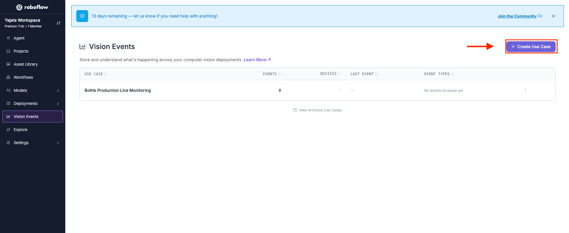
With that in place, add a Roboflow Vision Events block to the workflow. Set Input Image to the workflow's original inputs.image, and set Output Image to the text_display block's output image, so the event carries both the raw frame and the fully annotated one. Connect Predictions to the tracker's tracked_detections, set Event Type to Quality Check, and select the Bottle Production Line Monitoring use case you just created. Set Result to the custom Python block's qc_result output, and give Custom Metadata a small JSON object pulling in bottle_id, status, and defect_type from that same block.
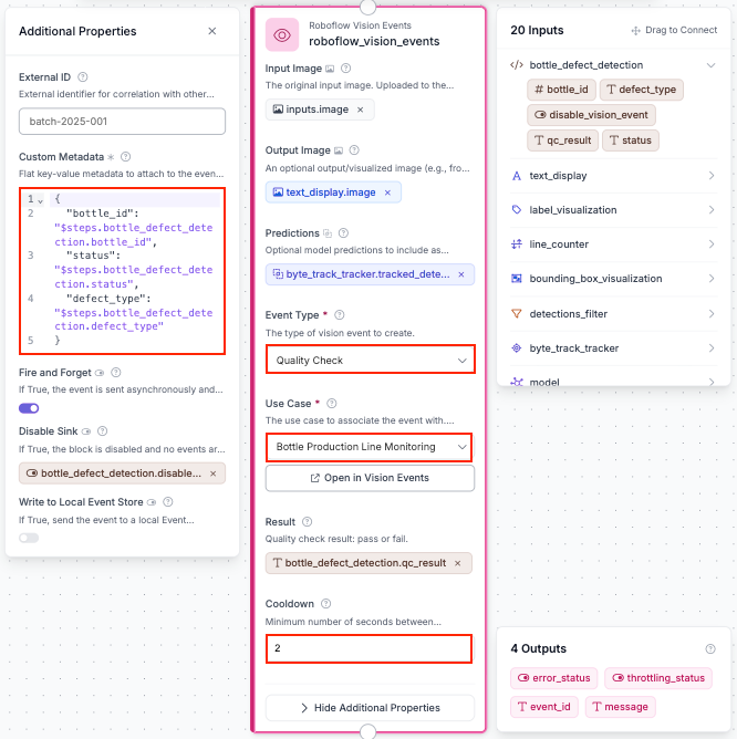
{
  "bottle_id": "$steps.bottle_defect_detection.bottle_id",
  "status": "$steps.bottle_defect_detection.status",
  "defect_type": "$steps.bottle_defect_detection.defect_type"
}
Two settings are doing quiet but important work here. Disable Sink is wired to the custom Python block's disable_vision_event output, which is what actually enforces the one-alert-per-bottle behavior from Block 8, since a True value there skips logging the event entirely. Cooldown is set to 2 seconds as a second layer of protection, giving the system a short buffer between events so a burst of near-simultaneous detections can't flood the dashboard even if two different bottles happen to fail back to back.
Step 8: Test the Workflow
Before trusting this on a real line, it's worth running it against a test video first. In the Workflow editor, use the preview panel to upload a short clip of bottles moving down a conveyor and step through it frame by frame, or run it end to end.
If a bottle without a cap or tag crosses the line and gets flagged, head back to the Vision Events dashboard and confirm the event actually landed there, with the right bottle ID, status, and defect type attached. That's the real test of whether the whole pipeline, from detection through tracking through inspection through logging, is actually working end to end, not just producing a nice-looking video.
Turning Detections into Action: Alerts and Integrations
Detecting a defect is only the first step in a production monitoring system. To create a complete manufacturing solution, vision results need to be connected to systems that can notify operators, record quality issues, or trigger actions on the production line.
In this workflow, the custom Python block processes tracked bottle detections and determines whether each product passes inspection. It checks whether the detected bottle contains the required components, such as a cap and tag, and outputs structured information including the bottle ID, inspection status, and defect type.
These results can then be recorded using Roboflow Vision Events. Each event creates a digital record of the inspection result, including information such as the detected defect, pass/fail status, timestamp, and the image showing the issue.
Once vision detections are converted into structured events, they can be connected to other manufacturing systems. For example, a failed bottle inspection could notify an operator, activate a reject mechanism to remove the product from the conveyor, stop the production line, or send quality data to a Manufacturing Execution System (MES). To learn more about connecting vision outputs to real-world systems, including PLCs, MES platforms, and Slack notifications, see Roboflow’s guide on turning vision detections into PLC, MES, and Slack alerts.
By connecting computer vision with existing manufacturing systems, AI inspection becomes more than a detection tool. It becomes an active part of the production process, helping teams respond to issues immediately and improve overall quality control.
Monitoring Computer Vision Systems at Scale
Deploying a computer vision model is only the beginning. As manufacturers expand vision systems across multiple production lines or facilities, monitoring model performance becomes important to ensure consistent results over time.
Production environments are constantly changing. Differences in lighting, camera positioning, product appearance, and manufacturing conditions can affect how a model performs after deployment. A model that performs well during initial testing may require adjustments as new situations appear on the factory floor.
Roboflow Vision Events help capture structured information from deployed workflows, allowing teams to understand what is happening across their production lines. In this bottle inspection system, each failed inspection can generate an event containing information such as the bottle ID, defect type, inspection result, and image evidence.
By analyzing these events over time, manufacturers can identify quality trends and respond to problems earlier. For example, teams can monitor whether the number of defective bottles exceeds a specific threshold, detect increases in a particular defect type, or compare inspection results across different production lines.
Instead of manually reviewing footage or discovering problems after products have already left the factory, manufacturers can use vision data to continuously monitor production quality and make faster decisions.
Getting Started with Production Line Monitoring
Ready to build your own computer vision application? Start with Roboflow for free and explore how AI-powered vision systems can help improve quality control, increase efficiency, and modernize manufacturing workflows.


Cite this Post
Use the following entry to cite this post in your research:
Yajat Mittal. (Jul 27, 2026). Production Line Monitoring With Camera AI. Roboflow Blog: https://blog.roboflow.com/production-line-monitoring-camera-ai/