
Manual PPE compliance checks do not scale across large sites or 24-hour operations, so this tutorial builds an end-to-end pipeline that detects whether each worker is wearing a helmet and safety vest and reports a live count of safe and unsafe workers on the video frame. You fork a PPE dataset from Roboflow Universe, train a custom RF-DETR object detection model on people, helmets, and vests, then assemble a Roboflow Workflow that adds ByteTrack for stable cross-frame tracking, spatial logic to match equipment to each person, and an on-screen safety tally.
Every year, thousands of workplace injuries occur because workers on construction sites and industrial floors are not wearing their required Personal Protective Equipment (PPE). Helmets prevent fatal head injuries, while high-visibility vests ensure workers are seen by machinery operators. Manual compliance checks are time-consuming, inconsistent, and impossible to scale across large sites or 24-hour operations.
This guide will walk you through an end-to-end computer vision solution to this problem, built on Roboflow, that automatically detects whether workers are wearing a helmet and a safety vest, and in real time reports a running count of safe and unsafe workers directly on the video frame. The system accepts any image or video feed as input, runs inference through a custom-trained RF-DETR object detection model, and overlays a live safety tally in the top corner of the output.
By the end of this tutorial, you will have:
- Forked and prepared a PPE dataset from Roboflow Universe
- Applied preprocessing and augmentations to the dataset for robust training
- Trained a custom RF-DETR object detection model to detect classes such as people, helmets, and vests
- Built a multi-step Roboflow Workflow that runs detection, tracking, visualization, and safety counting
- Tested the pipeline on a real-world construction site video
Automate PPE Detection with Roboflow
Step 1: Setting Up Your Roboflow Account
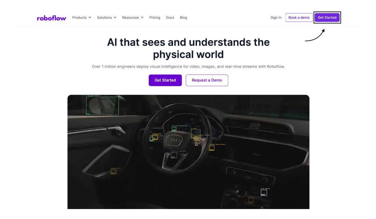
Everything in this project lives inside Roboflow, a platform that handles dataset management, model training, and deployment in a single environment. If you do not already have an account, go to roboflow.com and create a free account. The free tier is sufficient to complete every step described in this guide.
Step 2: Finding and Forking a Dataset on Roboflow Universe
The quality of any computer vision model depends heavily on the quality and diversity of its training data. Roboflow Universe is a public repository of over 500,000 open-source datasets covering thousands of detection tasks. Rather than annotating images from scratch, you can fork an existing dataset directly into your workspace and build on top of it.
Finding the Right Dataset
For this project, the source dataset used is:
Dataset: ppe_detection-dnfen by datasetppe-8juj2
This dataset includes annotated images of construction workers with labels covering several PPE categories: person, helmet, vest, no-helmet, no-vest, gloves, and others. For the purposes of this project, which is tracking whether each worker is safe, the three most important classes are person, helmet, and vest. The other classes (no-helmet, no-vest, gloves, etc.) add noise without improving the core safe/unsafe logic, and thus will later be filtered out in a workflow step.
Forking the Dataset
Forking creates a private copy of the dataset inside your own workspace so you can modify it by preprocessing, adding augmentations, and splitting ratios independently of the original.
- Open the dataset link above in your browser.
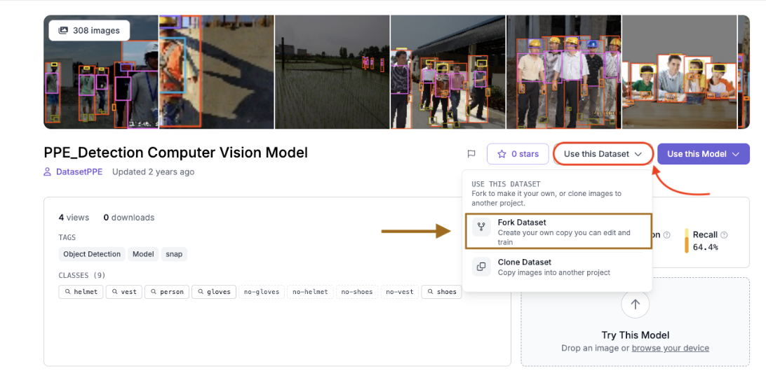
- Click the “Use this Dataset” button in the top right corner of the dataset page.
- Click the “Fork Dataset” button from the dropdown.
- Select your workspace as the destination.
- Roboflow copies all images and their annotations into a new project in your workspace.
A Note on Using Your Own Images
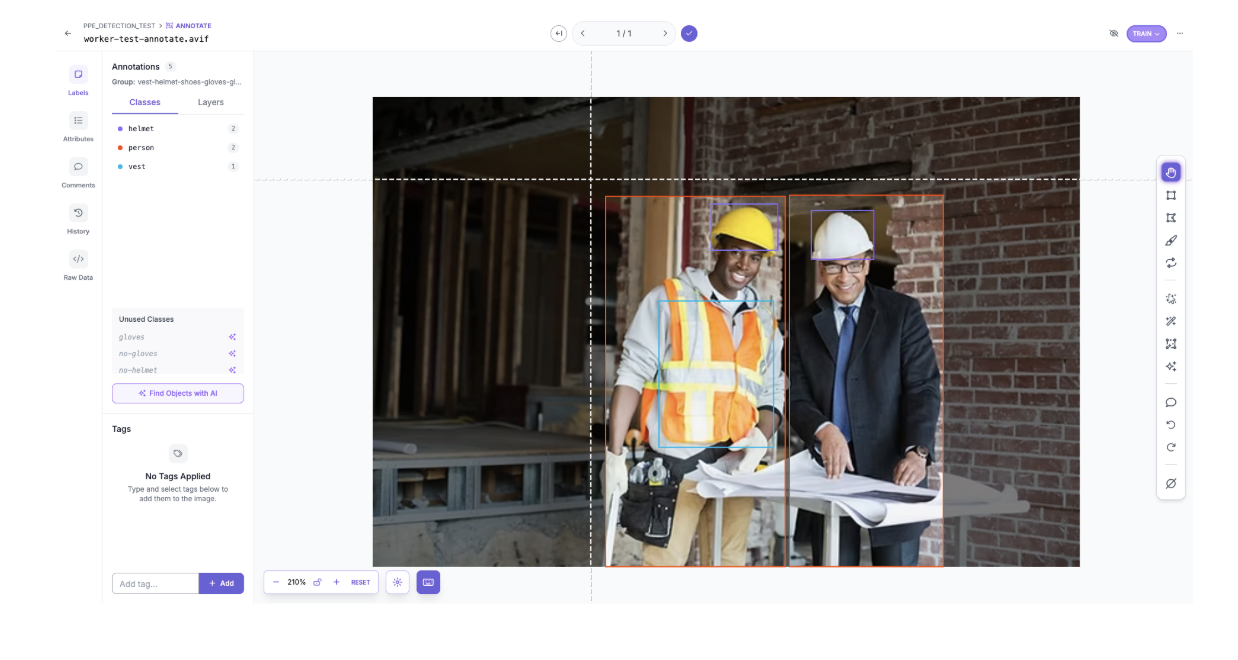
If you want to incorporate your own images in the dataset (for example, photos taken at your specific worksite), you can upload them directly into the forked project. Any new images will need to be annotated before they can be used for training. Roboflow provides a built-in annotation tool where you draw bounding boxes around objects and assign class labels. For PPE detection, you would draw a box around each worker and label it person, draw a box around each visible helmet and label it helmet, and draw a box around each visible vest and label it vest. Annotating even a few site-specific images can meaningfully improve the model's performance in your particular environment.
Step 3: Training the RF-DETR Model
What is RF-DETR?
RF-DETR (Roboflow Detection Transformer) is a real-time object detection model built by Roboflow. It’s based on a modern vision transformer backbone (specifically DINOv2), which means it looks at the whole image at once instead of piece by piece like older models. What makes it different from models like YOLO is how it detects objects. Instead of using anchor boxes and extra cleanup steps like non-maximum suppression, RF-DETR directly predicts bounding boxes in one pass. This makes the process simpler and more streamlined.
For something like PPE detection in construction footage, this works really well because the model is good at adapting to specific environments and recognizing objects like helmets and vests even in complex scenes.
Starting Training with Roboflow
To begin training a custom Roboflow model, follow the steps listed below:
- Open your project in Roboflow and then click the “Train” tab in the left sidebar.
- Select the “Custom Training” option as your engine.
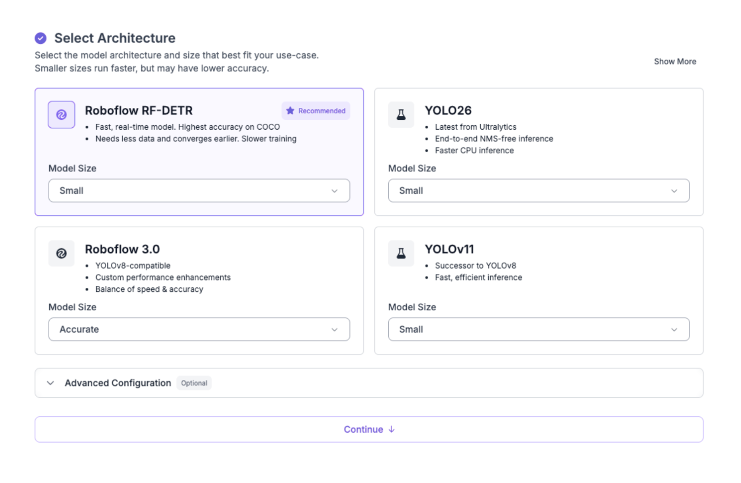
- When prompted to select a model architecture, choose RF-DETR from the list of available architectures, and select the Model Size as “Small”.
Step 4: Configuring the Train/Validation/Test Split
As one of the steps to training the model, you need to generate a dataset version for training, for which you need to define how the images are divided between training, validation, and test sets. These three splits serve distinct purposes:
- Training set: This is the main chunk of your data; it's what the model actually learns from. The more images you have here, the better.
- Validation set: The model never trains on these images. Instead, Roboflow uses them to check performance after each epoch, which helps you catch overfitting before it becomes a real problem.
Test set: These images are completely untouched until training is fully done. They give you an honest, unbiased read on how well your model actually performs.
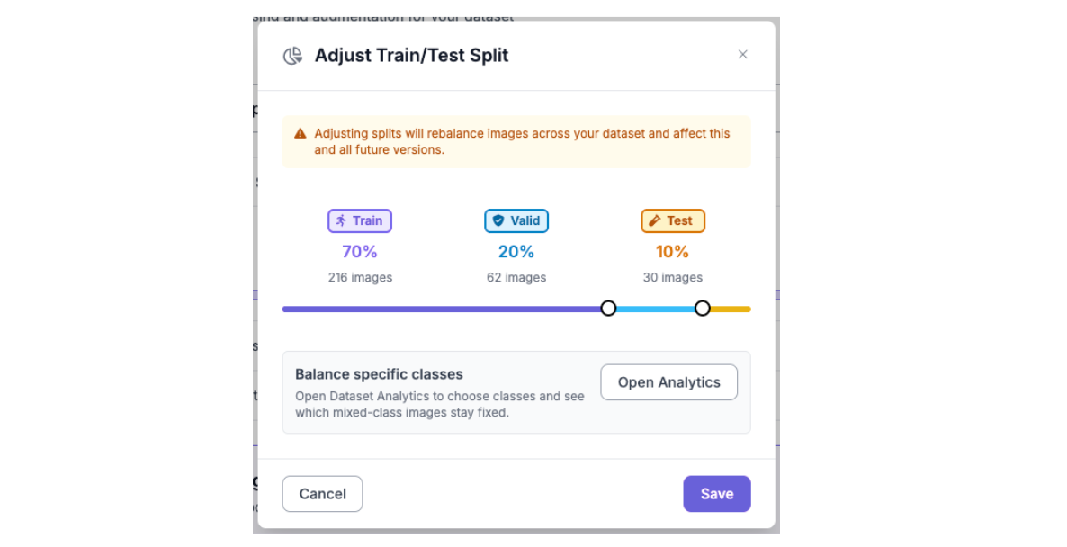
A standard split for this type of dataset is 70% training, 20% validation, and 10% test. Roboflow allows you to set these ratios when generating a new dataset version and will shuffle and assign images automatically. If the source dataset already has a defined split, Roboflow will respect it by default, but you can override it.
Step 5: Preprocessing and Augmentation
Roboflow lets you apply preprocessing transformations and data augmentation when generating a dataset version as well. These steps are essential to improve model accuracy.
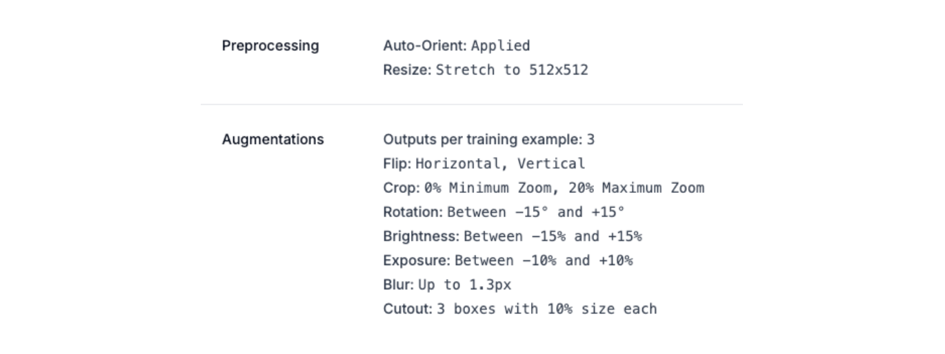
Preprocessing
Preprocessing transforms every image in the dataset into a consistent format before it is seen by the model.
- Auto-Orient: This corrects the orientation in photos taken on mobile devices or cameras. Without this step, images may be sideways or upside down, confusing the model.
- Resize (Stretch to 512×512): RF-DETR, like most transformer-based detection models, requires a fixed input resolution.
Augmentation
Applying augmentations artificially expands the training set by generating modified copies of each image. Setting outputs per training example to 3 means each original image produces three augmented variants, tripling the training set size. The following augmentations were applied:
- Horizontal and Vertical Flip: Simulates workers appearing on either side of a camera or in frames captured from overhead angles.
- Crop (0-20% zoom): Randomly crops into the image, forcing the model to detect PPE even when workers are partially out of frame or when the camera is positioned at a distance.
- Rotation (-15° to +15°): Accounts for cameras that are not perfectly level, or for workers bending forward and backward on uneven surfaces.
- Brightness (-15% to +15%): Helps the model perform well even under varying lighting conditions: direct sunlight, shade, or indoor lighting.
- Exposure (-10% to +10%): Randomly adjusts how bright or dark an image appears, simulating the over and underexposed footage you commonly get from outdoor CCTV cameras.
- Blur (up to 1.3px): Accounts for motion blur from fast-moving workers or lower-quality surveillance cameras operating at reduced framerates.
- Cutout (3 boxes at 10% size): Randomly masks out small rectangular regions of the image. This technique forces the model to make predictions based on partial visual information.
After following all steps 1-5, click “Start Training”. Training typically takes between 10 and 30 minutes, depending on dataset size and the number of epochs. You can monitor progress in real time from the training dashboard.
Step 6: Evaluating Training Results
Once training finishes, Roboflow displays a set of performance metrics alongside training graphs on the model page:
Here are the results from training this model:
- mAP@50: 79.2%
- Precision: 80.3%
- Recall: 80.1%
- F1: 80.2%
An mAP@50 of 79.2% tells us the model is doing a good job of finding and correctly labeling helmets, vests, and people across the test set. Precision and recall both coming in above 80% means the model is hitting a nice balance, it is not missing too many real detections but also not throwing out false positives constantly. The F1 score of 80.2% backs that up, showing the model is performing consistently rather than being strong in one area at the expense of the other.
For a safety monitoring use case, recall is the metric worth keeping an eye on. A missed unprotected worker is a much bigger problem than an occasional false alarm, so getting above 80% recall is a good place to be for real-world deployment.
The trained model is publicly available on Roboflow Universe here.
Step 7: Building the PPE Detection Workflow
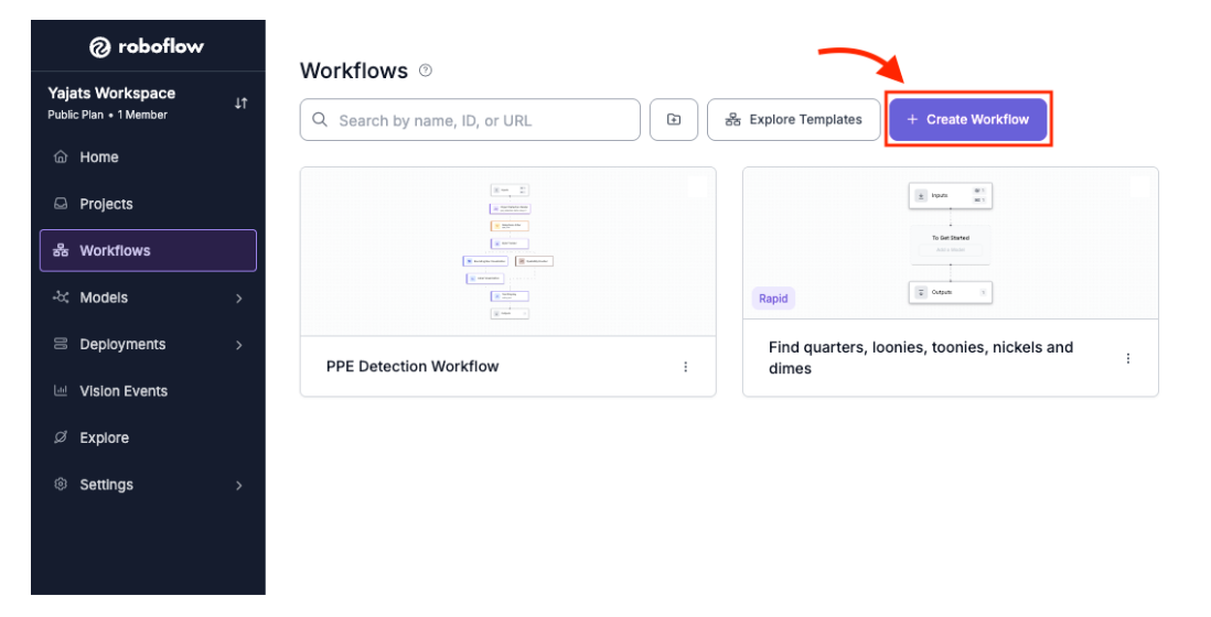
Roboflow Workflows is a visual, drag-and-drop tool for building computer vision pipelines. Instead of writing a lot of code to connect different parts of a system, you can simply add blocks to a canvas and link them together.
To create a new workflow, navigate to the “Workflows” tab in the left sidebar, then click “Create Workflow”. The canvas opens with an Input block and an Output block. You will build the pipeline by inserting blocks between them.
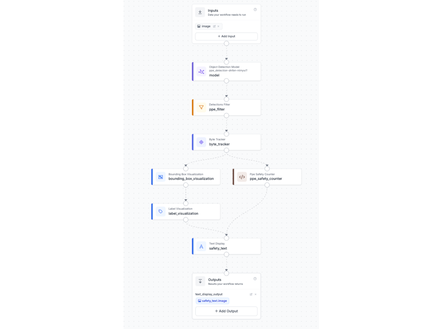
You can access the workflow for this project here, which shows the complete pipeline setup and how all the blocks are connected: PPE Detection Roboflow Workflow
This workflow is the exact setup used in the project, from running the RF-DETR model to tracking workers and calculating the live safe and unsafe counts.
The complete workflow for this project contains the following nine blocks, described in order:
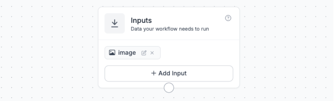
Block 1: Inputs
The Inputs block defines what data the workflow accepts. For this project, a single input called image is defined. This is a flexible input that can accept a still image file (JPEG, PNG) or a video frame. When the workflow is run against a video file in the Roboflow test interface, each video frame is passed through this block sequentially.
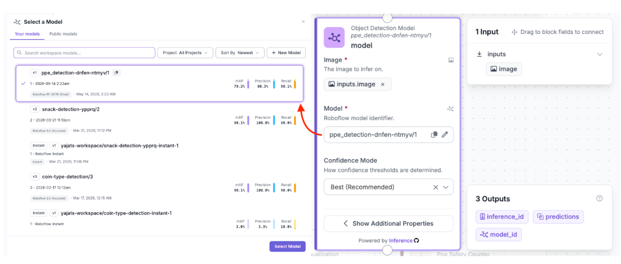
Block 2: Object Detection Model
The Object Detection Model block runs inference on each incoming image/video frame using the trained RF-DETR model. Click the block and select your model from the dropdown; it will appear under your workspace name. The block outputs a set of bounding box predictions (in xyxy coordinate format), confidence scores, and class name labels for every detected object in the frame. These raw detections include all classes that the model was trained to recognize.
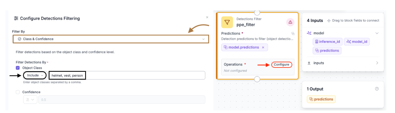
Block 3: Detections Filter
The raw detection output from the model includes every class in the training dataset. Since the goal is only to track classes such as person, helmet, and vest, the “Detections Filter” block is inserted immediately after the model to discard classes such as no-helmet, no-vest, gloves, etc.
To configure the filter, click the block to open the Configure Detections Filtering panel. Set Filter By to Class & Confidence. Under Filter Detections By, check Object Class, set the operator to Include, and enter the following in the class name field: helmet, vest, person
Any detection whose class name is not in this list is discarded before being passed downstream. The Confidence checkbox can be left unchecked for now; the model's default confidence threshold is sufficient for most use cases, but you can enable it and set a minimum score (e.g. 0.5) if you are seeing too many low-confidence false positives.
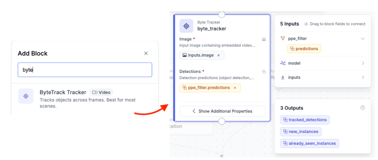
Block 4: Byte Tracker
Object detectors are stateless, which means each frame is processed on its own. The model has no understanding of whether a person detected in frame 100 is the same one detected in frame 101. For a live safety counter, this can cause issues. If a worker briefly disappears or is missed, they might get counted again when they reappear.
In the Roboflow Workflow, the ByteTrack block helps solve this. It takes the filtered detections along with the video frame (which includes metadata like frame order) and assigns each object a tracker_id. This ID stays consistent across frames for the same person, so instead of treating every frame separately, the system can actually track individual workers over time.
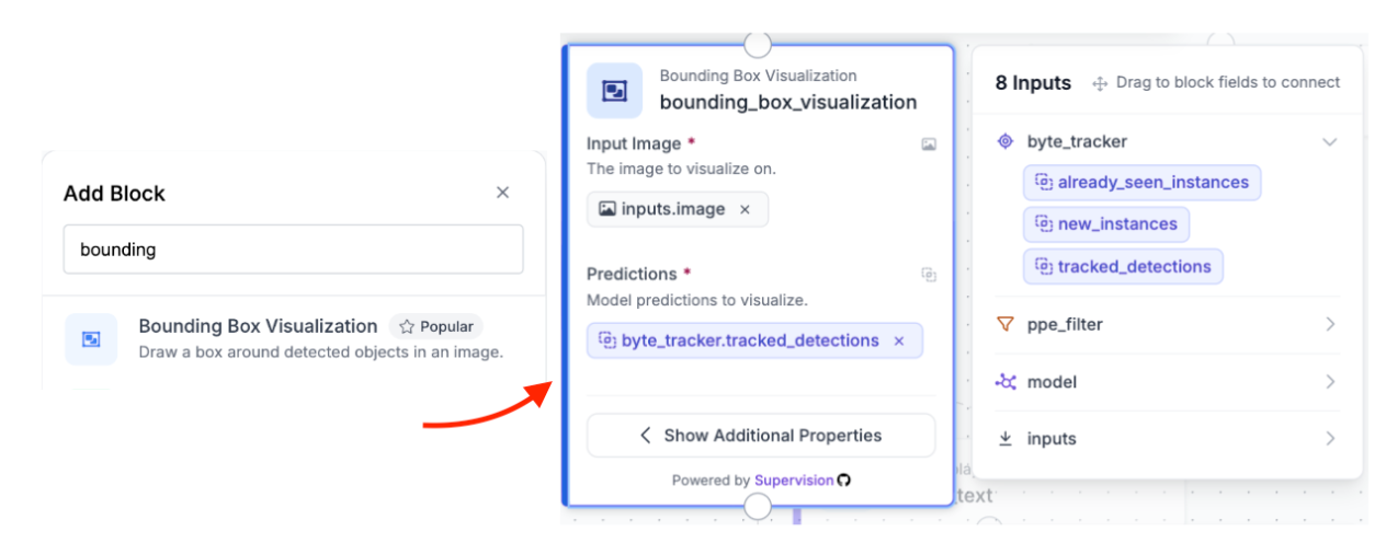
Block 5: Bounding Box Visualization
The Bounding Box Visualization block draws colored bounding boxes around each tracked detection on the image. It takes the image from the Input block and the tracked detections from the Byte Tracker block. Each detected object receives a color-coded rectangle drawn around it according to its assigned class. This visual layer makes the output immediately interpretable, allowing you to see exactly which workers, helmets, and vests have been detected and where.
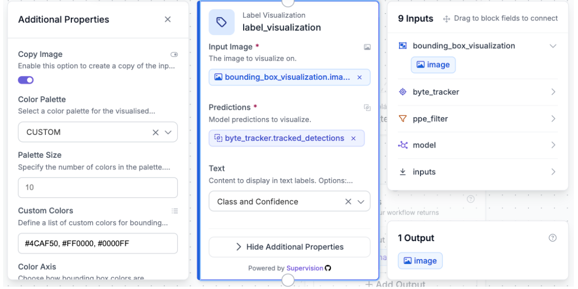
Block 6: Label Visualization
The Label Visualization block is used after the Bounding Box Visualization block. It overlays text labels (class name and confidence score) directly onto each bounding box on the image. This is what produces the readable person, helmet, and vest labels you see on the final output frame. The block takes the image from the bounding box step as its input image, which is important as each visualization block takes the previous block's output image to stack annotations on top of each other.
Block 7: PPE Safety Counter - Custom Code Block
This is the main logic block in the pipeline. In Roboflow Workflows, you can use Custom Python Blocks to write a simple run() function that runs as part of the workflow. This block takes in the filtered and tracked detections from ByteTrack and returns a JSON output with two values: safe_count and unsafe_count.
The safety logic works as follows:
- All detections are iterated and separated into three lists by class name: persons, helmets, and vests.
- For each detected person, the code checks whether any helmet's center point falls inside that person's bounding box, and whether any vest's center point also falls inside that person's bounding box.
- A person is considered safe only if both conditions are true: a helmet and a vest are detected within their bounding box. Otherwise, they are counted as unsafe.
Here is the full custom Python code for the block:
def run(self, predictions):
    if predictions is None or not hasattr(predictions, 'data') or predictions.data is None:
        return {"safe_count": 0, "unsafe_count": 0}

    class_names = predictions.data.get('class_name', [])

    if hasattr(predictions, 'xyxy'):
        bboxes = predictions.xyxy
    else:
        bboxes = []

    if len(bboxes) == 0 or len(class_names) == 0:
        return {"safe_count": 0, "unsafe_count": 0}

    persons = []
    helmets = []
    vests = []

    for i in range(min(len(class_names), len(bboxes))):
        cls = str(class_names[i]).strip().lower()
        bbox = bboxes[i]

        if cls == 'person':
            persons.append(bbox)
        elif cls == 'helmet':
            helmets.append(bbox)
        elif cls == 'vest':
            vests.append(bbox)

    def center_in(boxA, boxB):
        cx = (boxA[0] + boxA[2]) / 2
        cy = (boxA[1] + boxA[3]) / 2
        return (boxB[0] <= cx <= boxB[2]) and (boxB[1] <= cy <= boxB[3])

    safe = 0
    unsafe = 0

    for person in persons:
        has_helmet = any(center_in(h, person) for h in helmets)
        has_vest = any(center_in(v, person) for v in vests)

        if has_helmet and has_vest:
            safe += 1
        else:
            unsafe += 1

    return {"safe_count": safe, "unsafe_count": unsafe}
The center_in helper function determines whether the center point of one bounding box (the helmet or vest) falls inside another bounding box (the person). This is an easy and effective way to associate PPE items with the specific worker wearing them, even when multiple workers are present in the same frame.
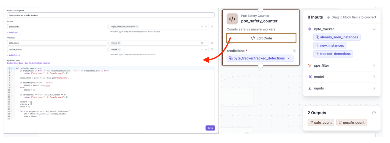
Note: There is a section where you can define the inputs and outputs, as shown in the image above. In this case, the input is predictions (of type object_detection_prediction), and the outputs are safe_count and unsafe_count, both returned as integers.
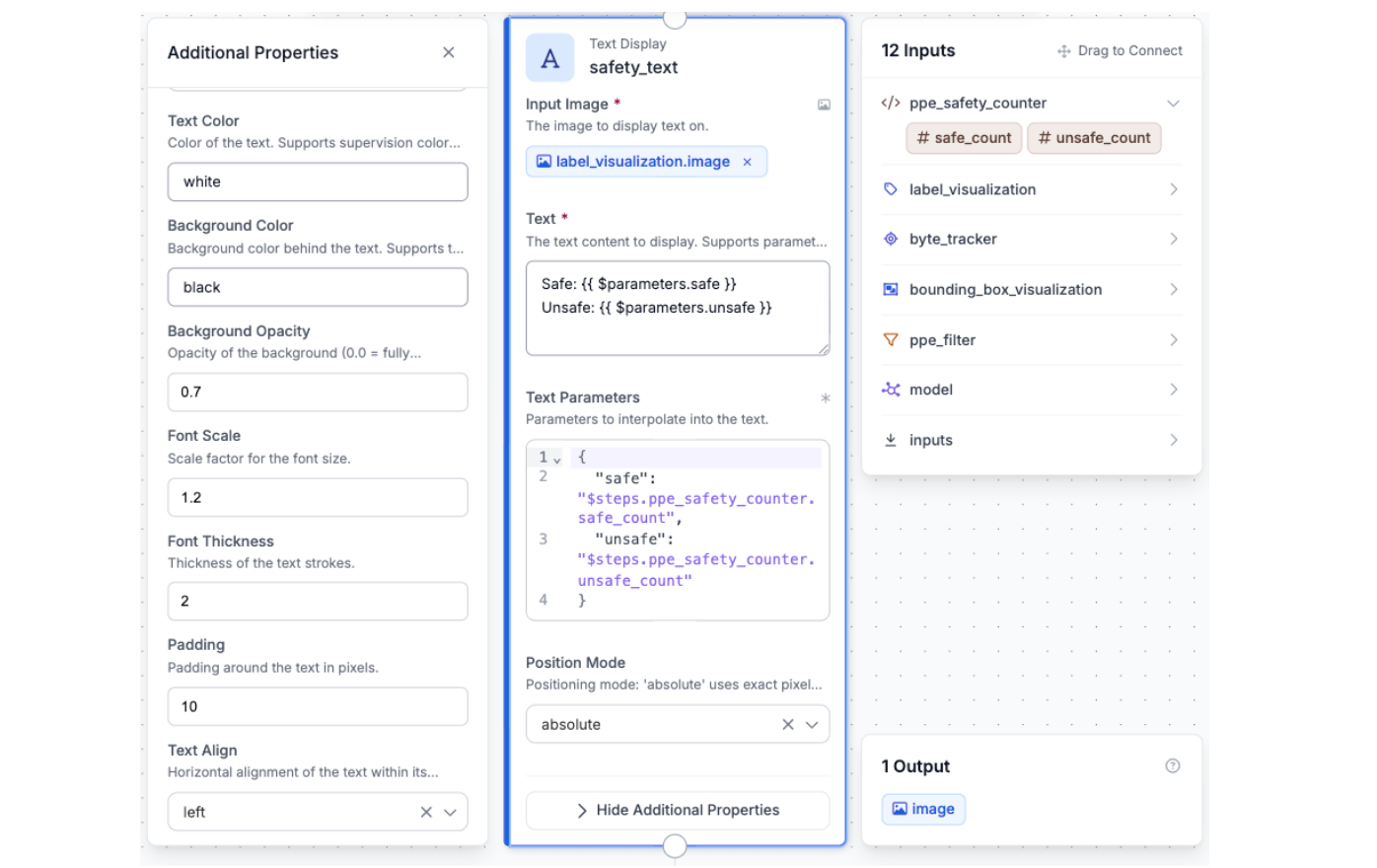
Block 8: Text Display
The Text Display block formats the safe_count and unsafe_count values returned by the custom code block into a human-readable string and overlays it on the output image. It uses a template like this:
Safe: {{ $parameters.safe }}
Unsafe: {{ $parameters.unsafe }}
These values are passed in from the previous step using the bindings $steps.ppe_safety_counter.safe_count and $steps.ppe_safety_counter.unsafe_count.
The final text is shown in the corner of each frame, so anyone watching the feed can instantly see how many workers are safe or unsafe at that moment.
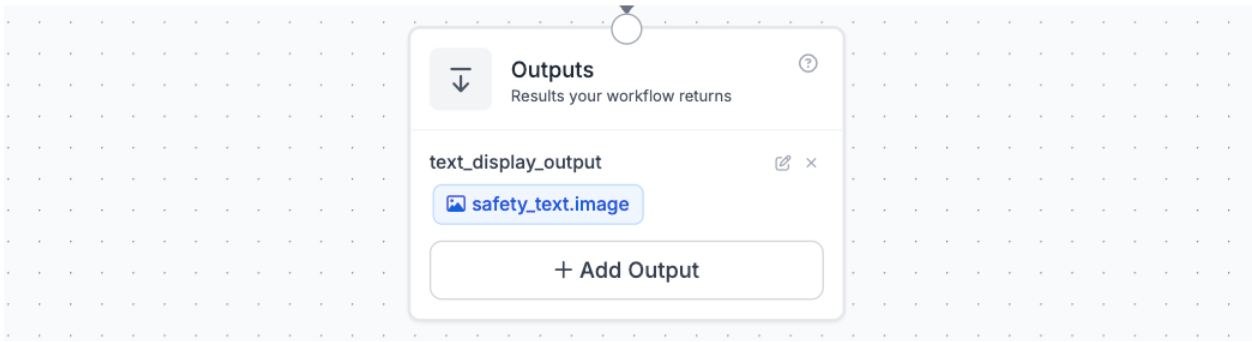
Block 9: Configuring Outputs
The Outputs block defines what the workflow sends back after running. For this project, the output is safety_text.image, which is the fully annotated video frame or image showing bounding boxes, class labels, and the safe/unsafe counter overlay.
To add an output, click “Add Output” in the Outputs block, choose whether it should be an image or data output, and then select the relevant step from the dropdown. It’s also helpful to give each output a clear name so it’s easy to understand when you look at the response.
Step 8: Testing the Workflow
With all blocks connected and configured, click the run button in the top right corner of the Workflows editor. Roboflow opens a test panel where you can upload an image or a short video clip.
For a meaningful test, use a video clip that includes multiple workers, ideally some wearing full PPE and some with a missing helmet or vest. Good sources for royalty-free construction site video include Pexels and Pixabay. Upload the video and click Run.
Roboflow processes the video frame by frame through the entire pipeline and returns the annotated output. You should see:
- Colored bounding boxes around each detected worker, helmet, and vest.
- Class labels overlaid on each bounding box.
- A text overlay in the corner of the frame showing the current Safe and Unsafe worker counts, updating on every frame.
How the Full Pipeline Fits Together
Each block in the workflow has a specific role, and the order matters. Here is a summary of data flow through the full pipeline:
- A video enters through the Inputs block as an image with embedded video metadata.
- The RF-DETR Object Detection Model block runs inference and outputs raw bounding box predictions for all detected classes.
- The Detections Filter block discards any detection that is not person, helmet, or vest.
- The Byte Tracker block assigns stable tracker IDs to each detection and maintains them across frames.
- The Bounding Box Visualization block draws boxes on the image.
- The Label Visualization block stacks class labels on top of the boxes.
- The PPE Safety Counter custom code block computes the safe and unsafe worker counts for that frame.
- The Text Display block renders the counts onto the annotated frame.
- The Outputs block returns the image/video with all the annotations.
Alternative: Building the Workflow with the Roboflow Agent
If you want a faster way to get started, Roboflow has a built-in Agent panel on the left side of the Workflows editor. Instead of adding and configuring each block manually, you can just describe what you want and the agent will build the pipeline for you.
Open the Agent panel and enter the following prompt:
"Use the ppe_detection-dnfen-ntmyv/1 model to detect objects in the input image. Then add a Detections Filter block called ppe_filter to include only the classes: helmet, vest, and person. Connect that to a Byte Tracker block called byte_tracker to maintain consistent IDs across video frames. From the Byte Tracker, split into two parallel branches. In the first branch, add a Bounding Box Visualization block called bounding_box_visualization, then connect that to a Label Visualization block called label_visualization. In the second branch, add a Custom Python Code block called ppe_safety_counter that takes the tracked predictions, separates detections into persons, helmets, and vests, and for each person checks whether a helmet and vest center point fall inside their bounding box, returning safe_count and unsafe_count as integers. Then merge both branches into a Text Display block called safety_text that overlays 'Safe: {safe_count} Unsafe: {unsafe_count}' onto the annotated image. Set the outputs to safety_text.image."
The agent will generate the workflow automatically. You may still need to go in and make small adjustments, but it gets you most of the way there without touching a single block manually.
PPE Detection Conclusion
In this project, we built a real-time PPE detection system that can monitor whether workers are wearing helmets and safety vests directly from a video feed. Using Roboflow, we went from a public dataset to a trained RF-DETR model, and then connected everything together using Workflows to create a full pipeline.
Along the way, we kept the system simple and focused. By only detecting people, helmets, and vests, and using a bit of spatial logic to match PPE to each worker, we were able to clearly determine who is safe and who is not. Adding ByteTrack made the system more stable by keeping track of workers across frames instead of treating every frame separately.
The end result is a system that runs on images or videos, draws bounding boxes around workers and their PPE, and shows a live count of safe and unsafe workers on screen. It is simple, practical, and something you can easily build on for real-world use.
If you want to take it further, you could add alerts, notifications, or expand it to detect more types of safety equipment. You can also fork the model and workflow to adapt it to your own environment and deploy it with minimal setup.
Written by Yajat Mittal
Cite this Post
Use the following entry to cite this post in your research:
Contributing Writer. (May 18, 2026). PPE Detection with AI: Real-Time Worker Safety Monitoring. Roboflow Blog: https://blog.roboflow.com/ppe-detection/