
Pose estimation is a computer vision technique that identifies and tracks key body joints in images or videos to understand posture and movement. For humans, it typically detects keypoints such as the nose, eyes, ears, shoulders, elbows, wrists, hips, knees, and ankles.
These keypoints can be connected to form a skeleton-like representation of the body, allowing systems to analyze how a person is positioned or moving over time.
By interpreting this structured body model, pose estimation enables a wide range of real-world applications, including exercise recognition (e.g., push-ups, squats, yoga poses), motion imitation, gesture-based interfaces, and advanced sports analytics.
The video below demonstrates pose estimation in action using a zero-shot pose estimation model, YOLO26-Pose.
What Is Zero-Shot Pose Estimation?
Zero-shot pose estimation refers to the ability of a model to predict human or object poses, such as joint locations and orientations, without being explicitly trained on a specific new dataset, environment, or task.
Instead of relying on task-specific fine-tuning, these models leverage generalized knowledge learned from large-scale training data to interpret and estimate poses in novel scenarios.
Zero-shot pose estimation models typically:
- Rely on pre-trained foundation architectures trained on large and diverse datasets to capture broad visual patterns and structural relationships.
- Exhibit strong generalization capabilities, allowing them to perform effectively in unseen environments, lighting conditions, and scenarios.
- Leverage transferable representations, reusing previously learned features to adapt to new tasks or domains without requiring additional retraining.
This capability makes zero-shot pose estimation particularly valuable in dynamic real-world settings, such as robotics and edge deployment, where collecting and annotating new data for every scenario is impractical.
Applications of Pose Estimation in Robotics
- Imitation Learning: Robots learn motion patterns by detecting and tracking human joint positions in real time.
- Collaborative Assembly: Robots use pose estimation to perform tasks alongside humans safely and efficiently.
- Assistive Support: Robots replicate or assist with human movements for rehabilitation or daily activities.
- Human-Robot Interaction: Robots understand gestures, anticipate intent, and respond safely to nearby movement.
- Teleoperation: Robots mirror the operator’s body movements for precise remote control.
- Adaptive Behavior: Pose estimation enables robots to act naturally, contextually, and responsively.
Why Use Roboflow Workflows for Zero-Shot Pose Estimation in Robotics?
Roboflow Workflows is a low-code, web-based platform that lets you visually build computer vision pipelines by connecting reusable blocks.
It includes pre-built blocks for tasks such as detection, classification, segmentation, tracking (e.g., ByteTrack), and integration with large models or business logic, which can be chained together to create end-to-end computer vision pipelines with little to no coding.
Here are the key reasons to use Roboflow Workflows for zero-shot pose estimation:
- Ready-to-Use Pose Estimation Models: Roboflow provides pre-deployed zero-shot pose estimation models in multiple size variants, allowing you to start immediately without any installation.
- Optimized Real-Time Edge Deployment: Supports local deployment on edge devices with optimized inference servers that run with minimal code, working within hardware constraints and ensuring low-latency performance for robotic control and human-robot interaction.
- Provides Built-In Tracking Blocks: Includes pre-implemented tracking algorithms, such as ByteTrack, as workflow blocks to ensure consistent keypoint tracking in multi-person or occluded scenes.
- Accelerates Experimentation and Iteration: Offers a visual workflow builder, dataset versioning, and quick redeployment to speed up robotics R&D and production cycles.
- Simplifies Model Training and Iteration: Makes dataset collection and training easier with automatic augmentation, dataset versioning, fine-tuning, and active learning blocks, enabling models to improve quickly.
- Simplifies Robotics System Integration: Supports RTSP streams, local cameras, and APIs, enabling seamless integration with robotics control pipelines.
Building a Zero-Shot Pose Estimation Workflow using YOLO26-Pose
Several open-source pose estimation models exist, including YOLO26-Pose, MediaPipe Pose, and OpenPose, each optimized for different performance profiles and deployment scenarios.
You can explore them in detail, with a comparison of their strengths, trade-offs, and ideal use cases here.
Among them, YOLO26-Pose stands out for its balance of speed and accuracy, making it well-suited for real-time edge applications, including robotics, without compromising precision.
In this blog, we will focus on using YOLO26-Pose for zero-shot pose estimation within Roboflow workflows and demonstrate how to deploy it effectively on edge devices for practical robotics applications.
This is the zero-shot pose estimation workflow we will create.
Step 1: Setup Your Roboflow Workflow
To get started, create a free account on Roboflow and log in. Then create a workspace, select “Workflows” from the left sidebar, and click the “Create Workflow” button.
This will open a modal like the one shown below, where you can choose from various templates for segmentation, OCR, background removal, and more.
In our case, we select “Build My Own,” which comes pre-integrated with an object detection model by default, as shown below:
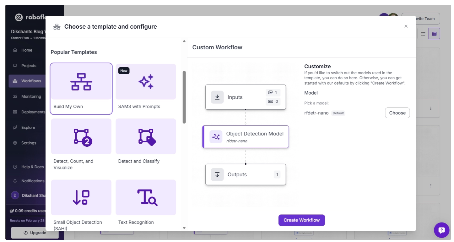
By default, the Object Detection Model block is set to RF-DETR (Nano variant). You can change this by clicking the “Choose” button, which opens a model selection pop-up.
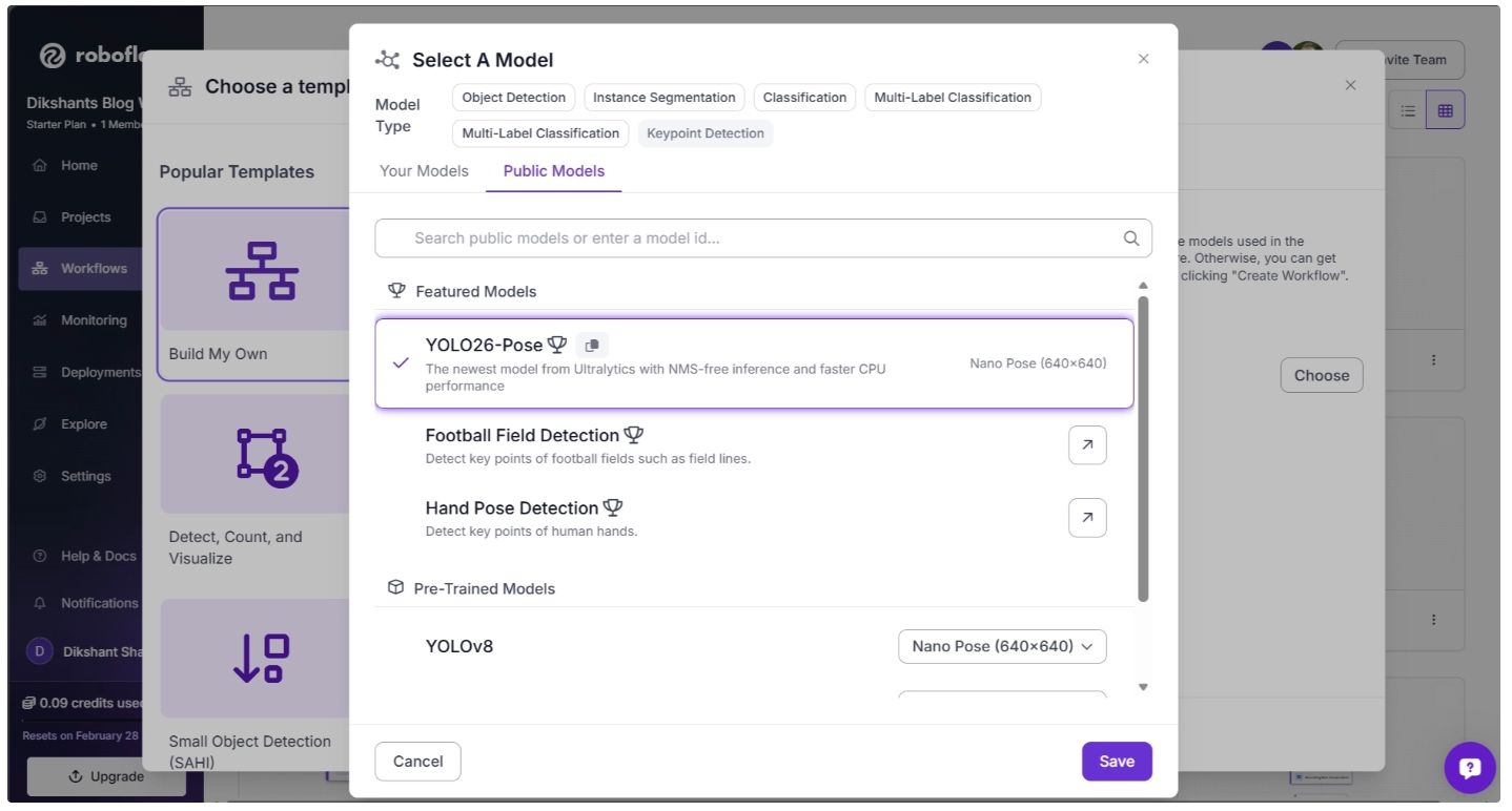
In the pop-up menu, set the Model Type to “Keypoint Detection.” Then, under Featured Models, select “YOLO26-Pose” and click Save, as shown below:
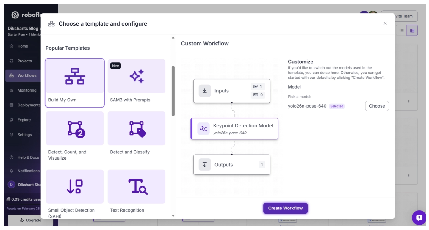
After you’ve selected the YOLO26-Pose model, click “Create Workflow,” as shown below, to create your workflow.
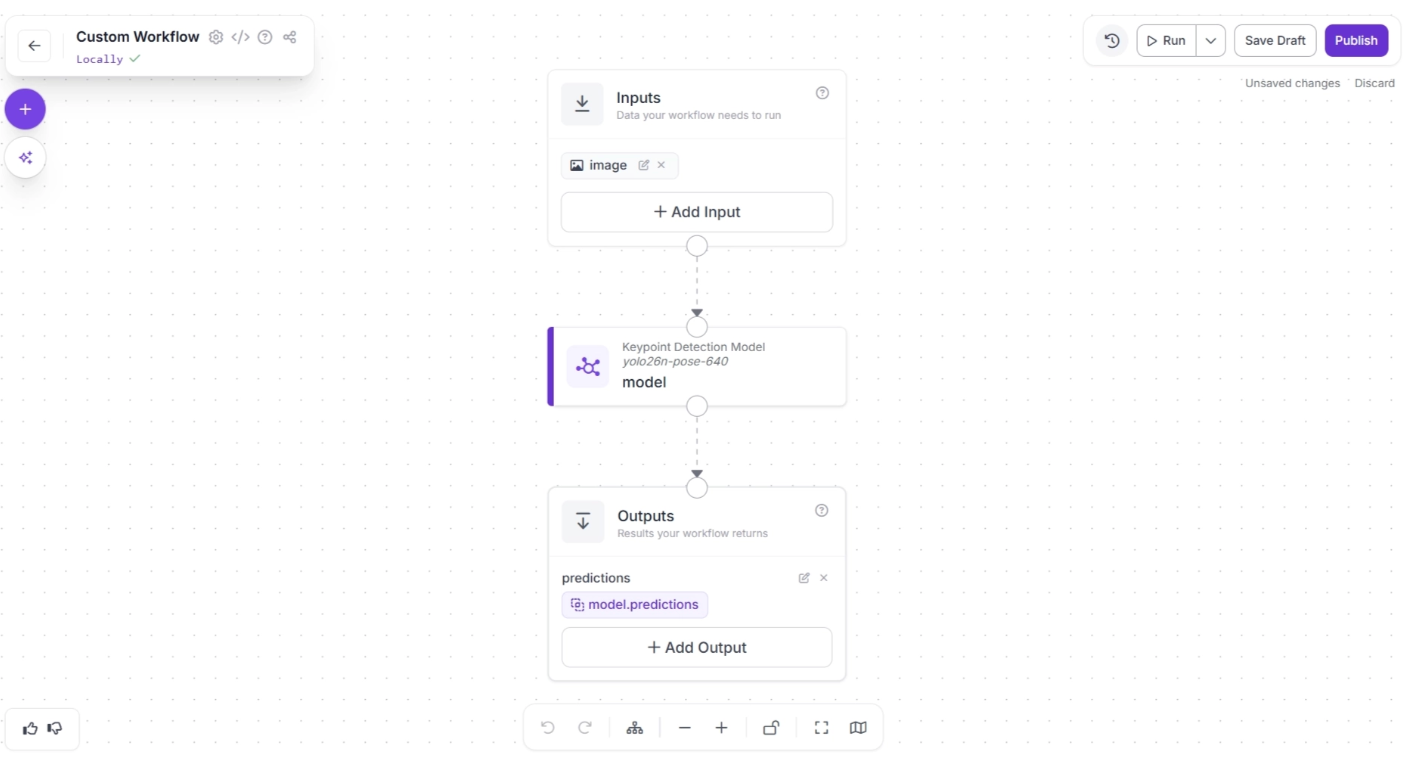
Then you’ll be taken to a blank workflow editor, ready to build your AI-powered workflow, where you’ll see three workflow blocks: Inputs, Outputs, and an Keypoint Detection Model as shown below:
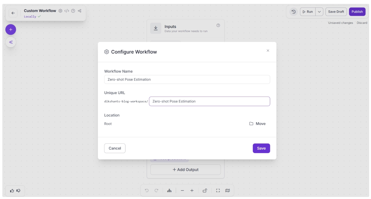
You can also configure the workflow name by clicking the ⚙️ icon in the top-left corner. This opens the workflow configuration modal, as shown below:
You can then return to the home page and, in the left sidebar under “Workflows,” open the renamed workflow to continue building.
Step 2: Add Byte Tracker
In order to enable tracking of people across video frames using the predictions from the Keypoint detection model (YOLO26-Pose), we add a Byte Tracker block to our workflow.
This block accepts detections and their corresponding video frames as input, initializing trackers for each detection based on configurable parameters like track activation threshold, lost track buffer, and minimum matching threshold.
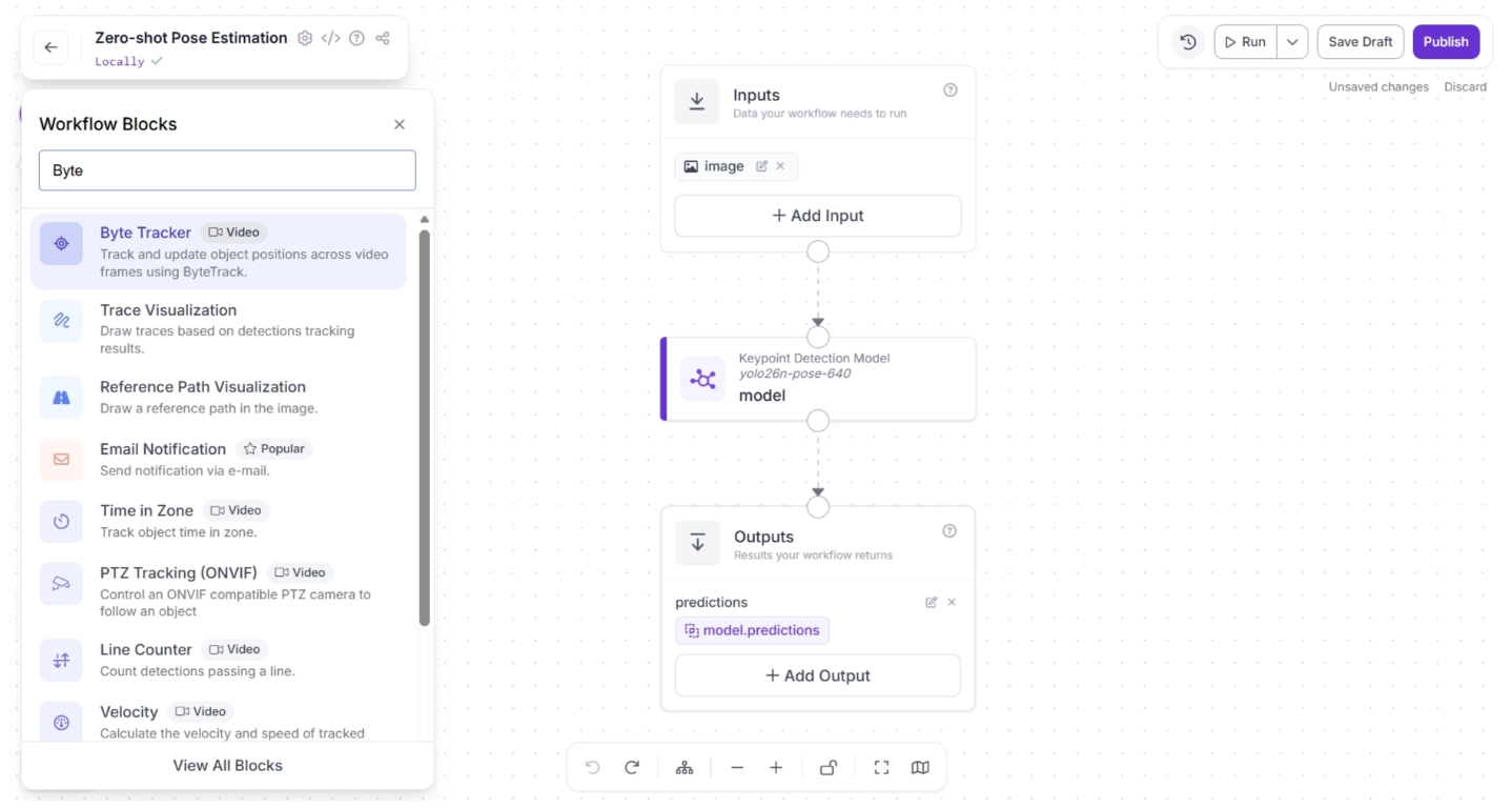
To add this block, click the “+” button in the top-left corner of the workflow canvas. A pop-up menu with workflow blocks will appear, as shown below. From there, search for “Byte Tracker” and select it to insert it into your workflow.
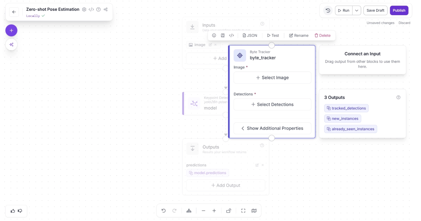
Once added, the block should appear on the canvas, as shown below:
Next, create a connection from the Keypoint Detection Model block to the Byte Tracker block, and another connection from Byte Tracker to the Outputs block. This ensures that the tracked persons detected by the keypoint detection model are also available as workflow outputs, allowing robotics systems to utilize the tracking data.
Your workflow should then look as shown below:
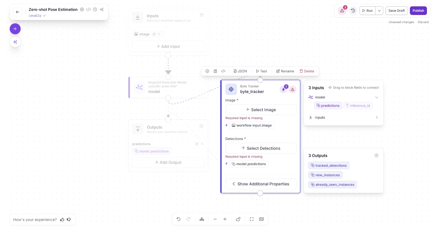
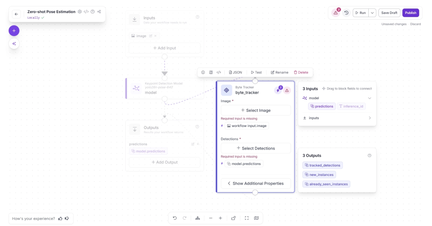
Click the lightning icon (⚡) in the top-right corner of the Byte Tracker block to accept “input suggestions.” When you connect one block to another, the downstream block receives the output from the upstream block, which can be used as input for its parameters.
The lightning icon automatically assigns these input values from the upstream block to the most likely parameters.
In the workflow below, upstream values such as the input image and model predictions are likely to be used by the Byte Tracker’s “Image” and “Detections” fields, so clicking the lightning icon (⚡) automatically assigns these input suggestions.
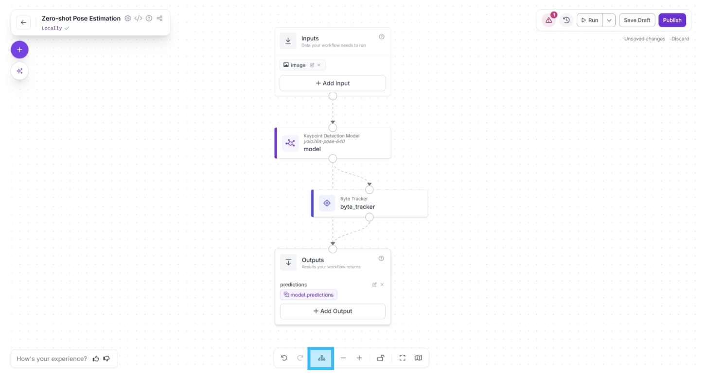
After completing these steps, use the Auto Layout button, located to the left of the Zoom In and Zoom Out controls in the bottom menu, to automatically organize the workflow layout.
Your workflow should then appear as shown below:
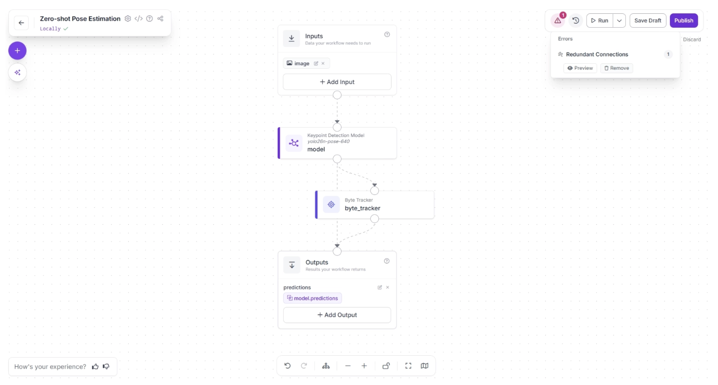
In the top-right corner menu of the workflow canvas, to the right of “Run,” a warning (⚠️) icon may appear. This indicates that there may be errors in your workflow.
For example, in our case, clicking the warning icon indicates a “Redundant connection.” In Roboflow workflows, the output of all upstream blocks is available to downstream blocks.
Therefore, the output of the Keypoint Detection Model should be available to the Outputs block through the Byte Tracker and then the Outputs block. A direct connection from the Keypoint Detection Model to the Outputs block is redundant.
You can automatically remove the redundant connection by clicking the “🗑️ Remove” button within the warning (⚠️) icon popup, as shown below:
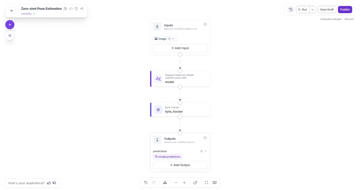
Your workflow should then appear as shown below:
Step 3: Add Keypoint Visualization
Roboflow Workflow provides a Keypoint Visualization block, allowing you to easily visualize the keypoints detected by the Keypoint Detection Model.
This visualization is primarily intended for developers, rather than the robot itself, helping them understand how the model interprets different poses and movements of a person.
It enables developers to more effectively configure and optimize their robotic systems.
To add this block, click the “+” button in the top-left corner of the workflow canvas. A popup menu with workflow blocks will appear, as shown below. From there, select the “Keypoint Visualization” block.
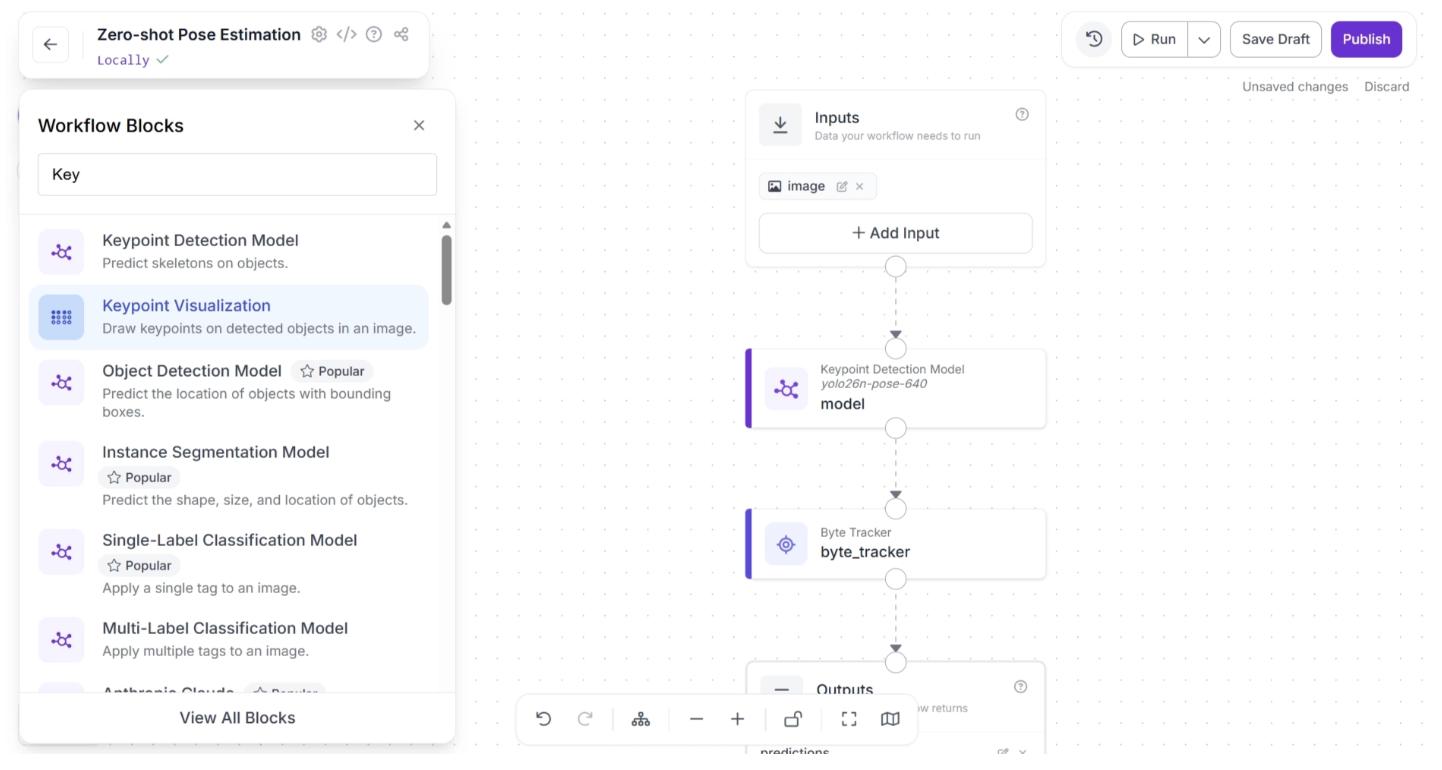
Once added, the block should appear on the canvas, as shown below:
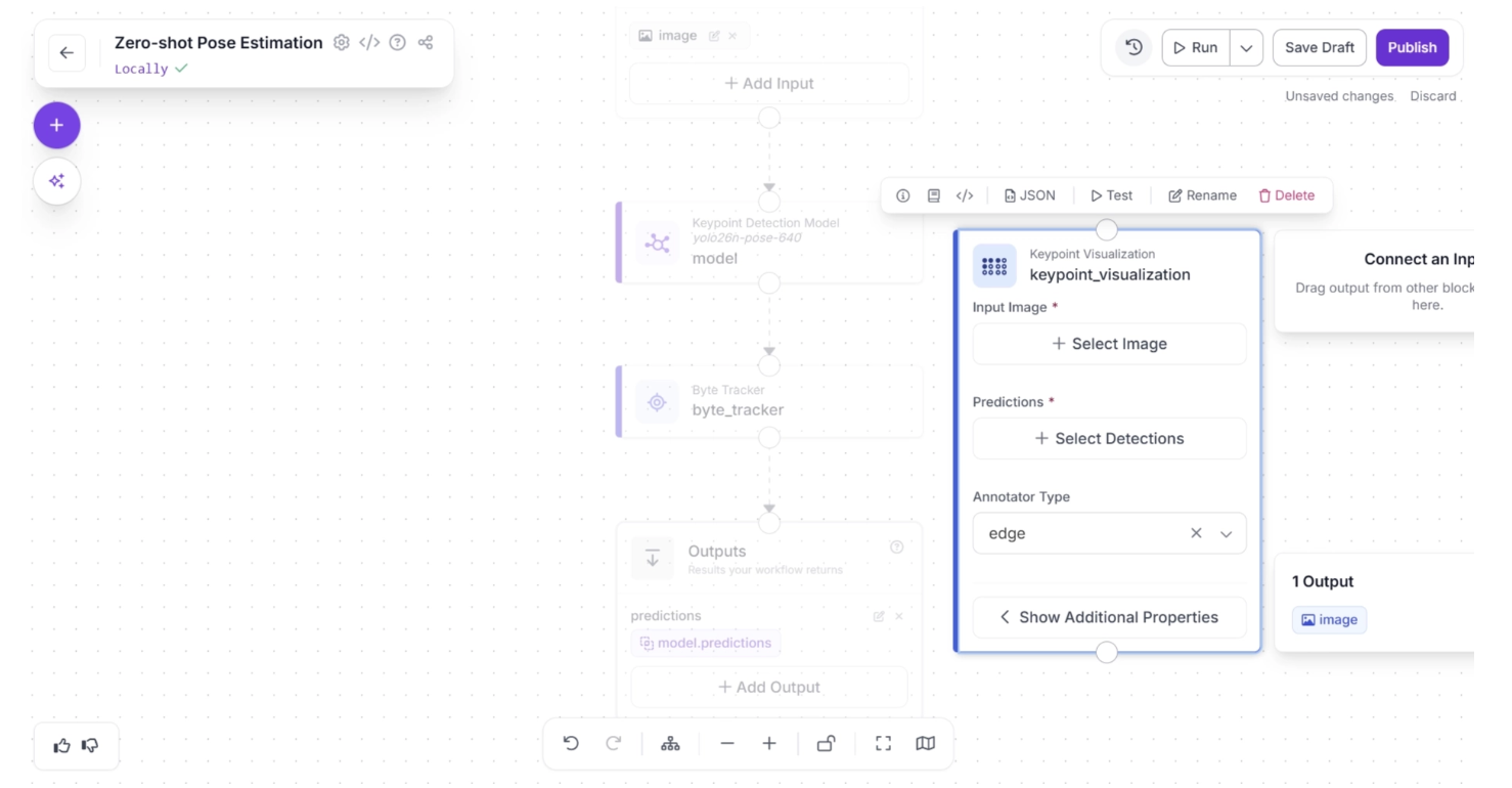
Next, create a connection from the Byte Tracker block to the Keypoint Visualization block, and another connection from Keypoint Visualization to the Outputs block. Your workflow should then look as shown below:
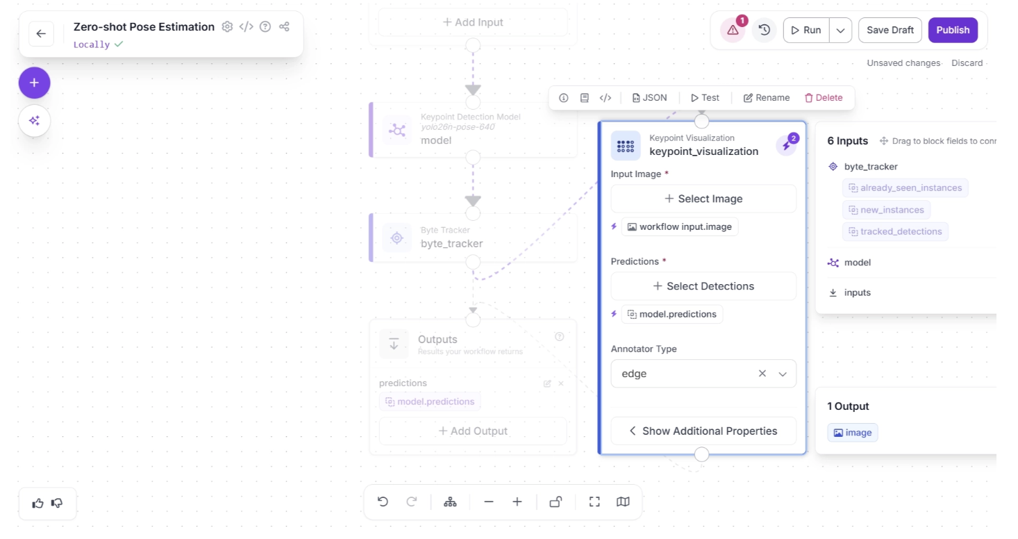
Then, accept the input suggestions by clicking the lightning icon (⚡) in the top-right corner of the Keypoint Visualization block. This automatically assigns the input values from the upstream block to the most appropriate parameters as shown below:
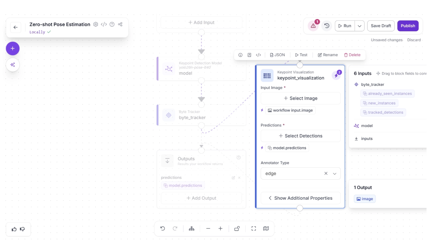
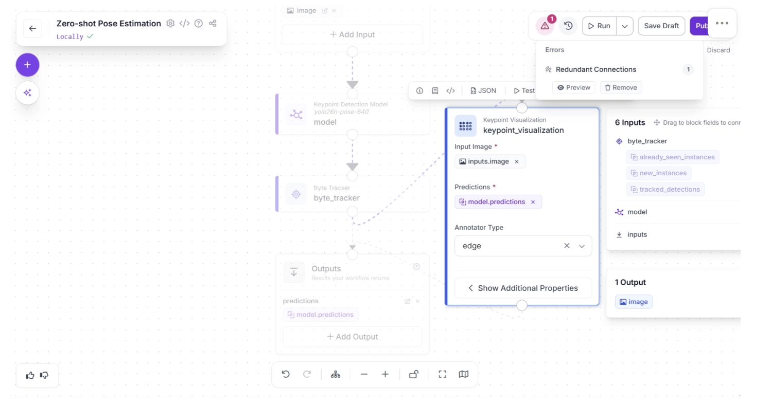
Now remove the redundant connection by clicking the “🗑️ Remove” button in the warning (⚠️) icon pop-up that appears in the top-right corner menu of the workflow canvas, to the right of the “Run” button, as shown below:
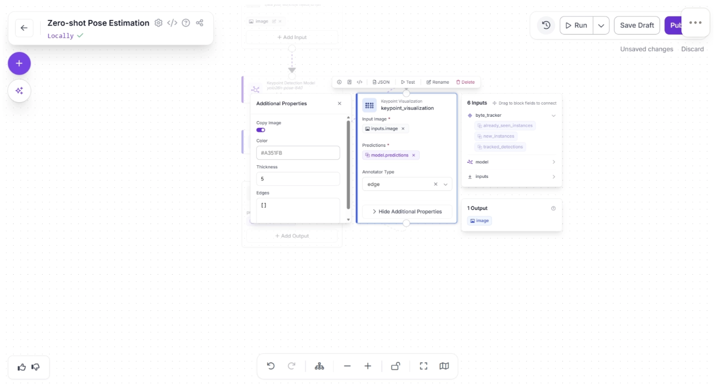
Inside the Keypoint Visualization block, under “Show Additional Properties,” set the thickness to 5, as shown below. The thickness determines how thick the visualized edges connecting the keypoints will appear.
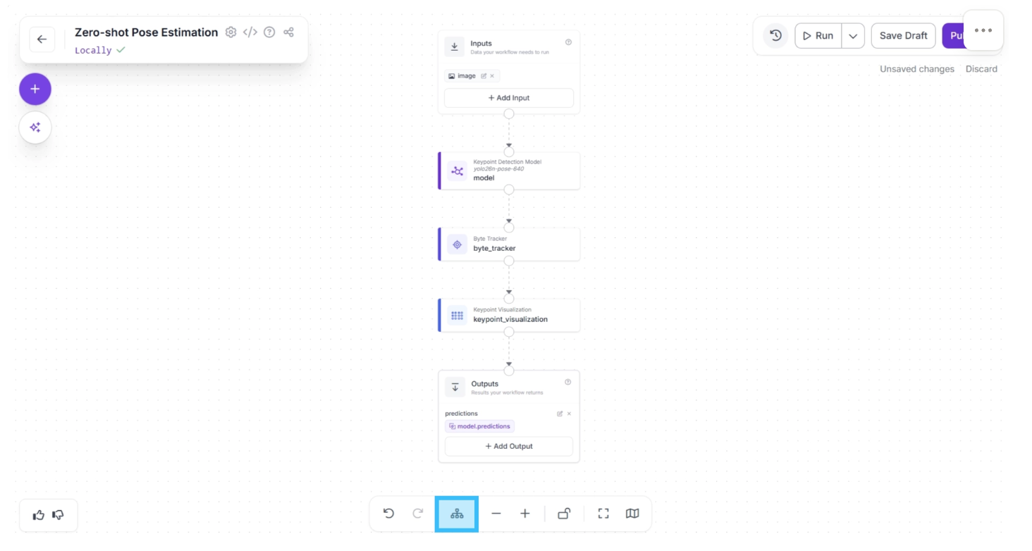
After completing these steps, use the Auto Layout button to automatically organize the workflow. Your workflow should then appear as shown below:
Step 4: Setup Outputs
The Outputs block has access to all outputs from upstream blocks and determines the workflow’s final output.
In our case, the workflow should output both the visualization and the pose detection model predictions (from byte tracker).
The visualization helps the developer better understand how the YOLO26-Pose model detects poses in a scene, making it easier to configure and fine-tune the detection model.
The predictions, on the other hand, are returned as JSON values (as shown in the example below), which a robot can use to interpret human posture and trigger appropriate actions.
{
	...
  "predictions": [
    {
	    ...
      "tracker_id": 1,
      "class": "person",
      "keypoints": [
        {
          "id": 0,
          "name": "nose",
          "x": 738,
          "y": 340,
          "confidence": 0.36
        },
        {
          "id": 1,
          "name": "left_eye",
          "x": 742,
          "y": 331,
          "confidence": 0.21
        },
        ...
      ],
      ...
    }
  ]
}
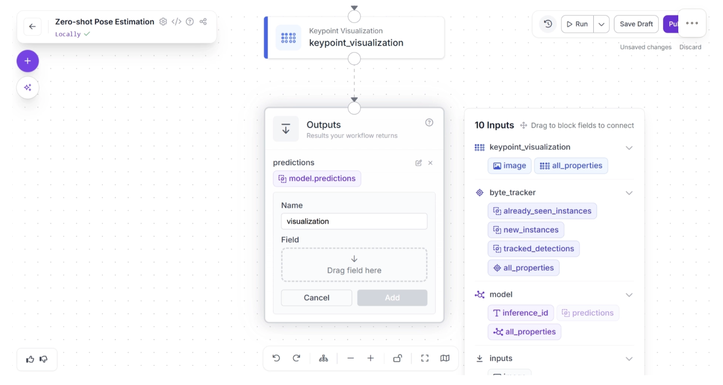
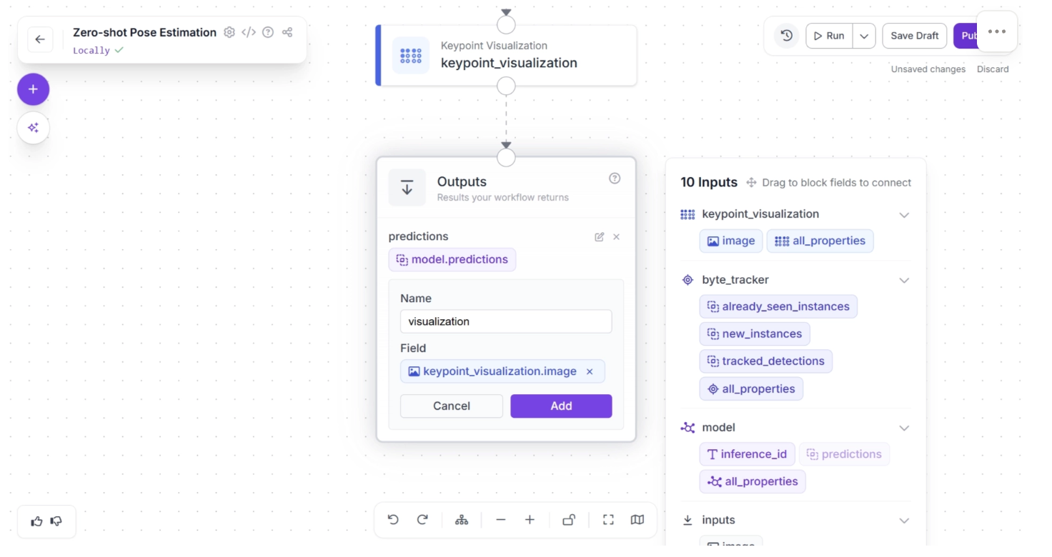
To do this, click on the Outputs block and enter “visualization” in the Name field. In the Field section, drag and drop the “image” from the “keypoint_visualization” section of the popup that appears when the Outputs block is clicked, then click Add, as shown below:
Your workflow should then look as shown below:
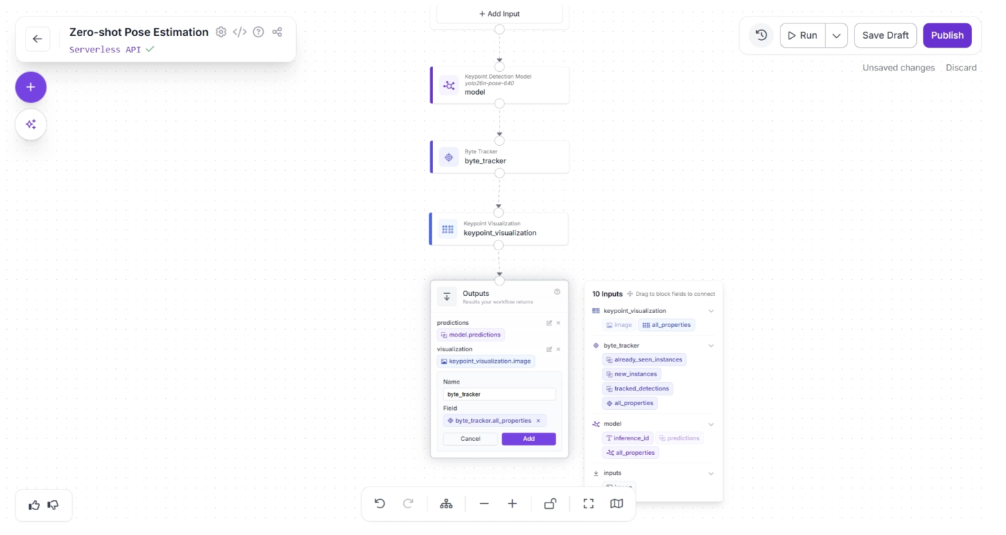
Similarly, enter “byte_tracker” in the Name field. In the Field section, drag and drop “all_properties” from the “byte_tracker” section of the popup that appears when the Outputs block is clicked, then click Add, as shown below:
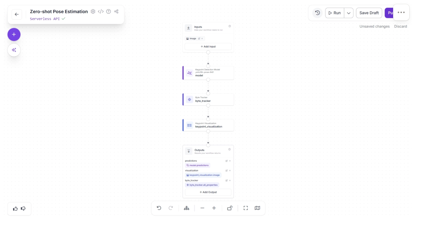
Your workflow should then look as shown below. This is the final workflow.
Step 5: Deployment
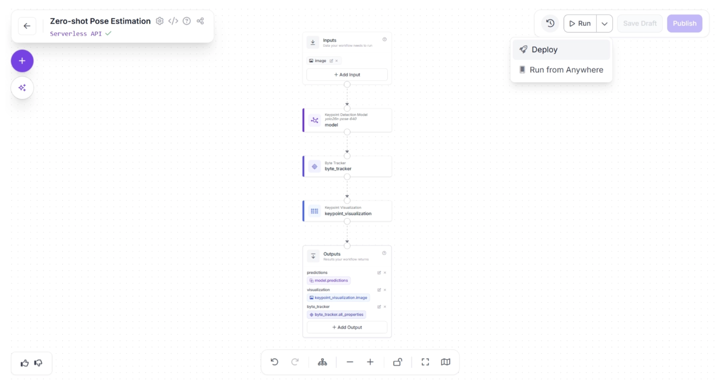
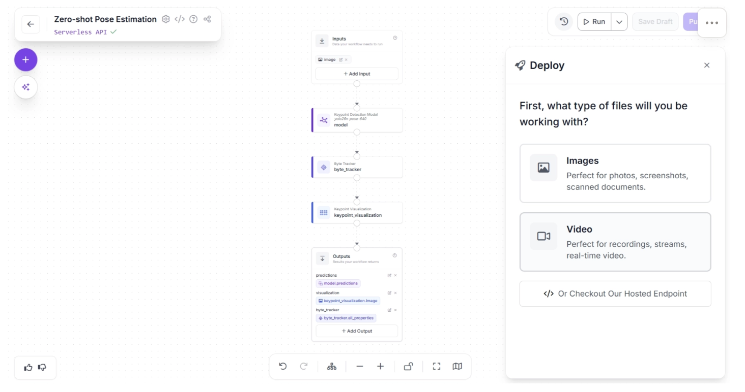
Roboflow provides several deployment options for workflows. You can access them by clicking the dropdown icon next to the “Run” button in the top-right corner of the canvas, then selecting the “Deploy” option, as shown below:
The “Deploy” button offers deployment options for both images and videos. Since robotics applications typically use a live video feed as input, we can select Video.
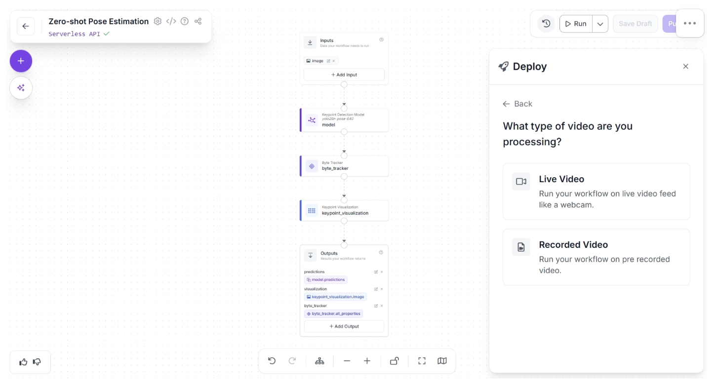
Under “Video,” you can choose between “Live Video” and “Recorded Video.” For robotics applications, “Live Video” is the more appropriate option, so select it as shown below:
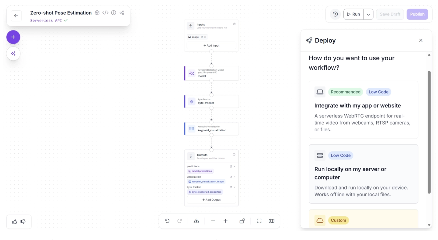
You can then choose a deployment source, either in an app or locally on a computer. For robotics applications, deployment typically relies on edge inference, so select the “Run locally on my server or computer” option:
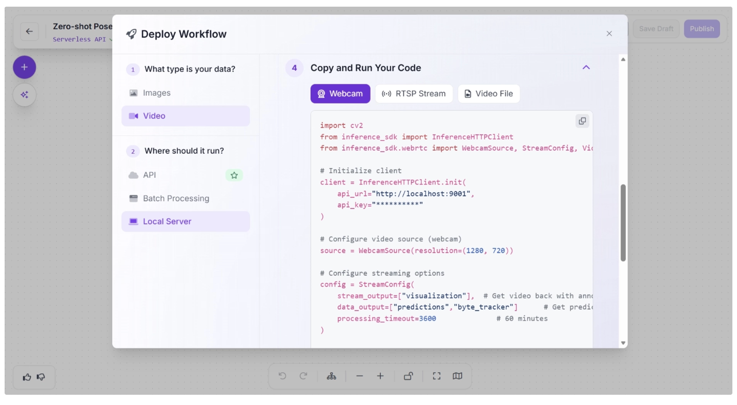
A popup will then appear, as shown below, allowing you to run the workflow locally on an edge device. This involves setting up an inference server on the edge device by installing the required packages and running the inference script.
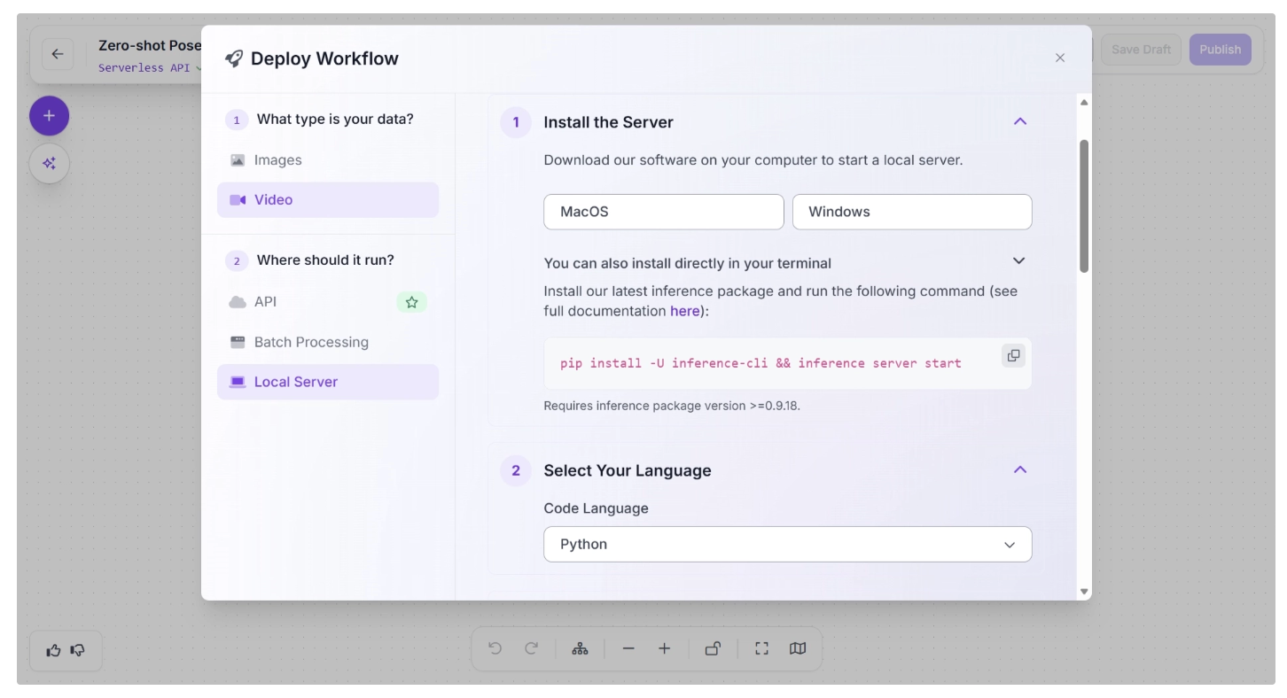
After you have successfully run the inference server, the “Copy and Run Your Code” section will display the inference script generated for the programming language you selected.
This script can be used to run inference on the completed workflow on your edge device using a webcam, an RTSP stream, or a video file.
Comparing Edge and Cloud Deployment for Zero-Shot Pose Estimation in Robotics
When deploying zero-shot pose estimation systems in robotics, one of the most important decisions is whether to run the workflow on the edge or in the cloud.
In robotics, both deployment targets are necessary, and where they are used depends on the specific use case.
Edge Deployment
In edge deployment, the pose estimation model runs directly on the robot, such as an embedded device (e.g., NVIDIA Jetson, Raspberry Pi, etc.).
For robotics, edge deployment is often the preferred choice when:
- Low latency is critical: Real-time control loops require inference in just a few milliseconds. Sending data to a remote server introduces unpredictable network delays.
- Closed-loop control is involved: Robotic arms, mobile robots, and drones rely on immediate feedback from vision systems to adjust movement.
- Connectivity is unreliable or unavailable: Warehouses, factories, underground environments, and remote locations may not have stable internet access.
- Data privacy matters: Sensitive visual data (industrial processes, proprietary environments) remains on-device.
However, edge systems are constrained by hardware. Large foundation models used in zero-shot pose estimation may be too heavy to run efficiently on embedded devices.
This often requires model optimization techniques such as quantization, pruning, knowledge distillation, or smaller variant size.
While edge systems may sacrifice some model size or complexity, they provide the determinism and responsiveness that robotics applications demand.
Cloud Deployment
In cloud deployment, image or video data from the robot is sent to remote servers for inference. The cloud offers access to powerful GPUs and scalable infrastructure.
Cloud deployment is advantageous when:
- Fleet-wide coordination is required: A central system can aggregate pose data from multiple robots for planning or monitoring.
- Large models are required: Transformer-based vision models or large foundation models may exceed edge hardware capabilities.
- Batch processing or analytics is needed: Historical robot data can be processed for training, improvement, or inspection tasks.
The main limitation is latency. Even small network delays can make cloud inference unsuitable for real-time robotic control.
Additionally, cloud systems depend on reliable connectivity and incur ongoing operational costs.
The Hybrid Approach
In practice, many modern robotics systems adopt a hybrid architecture:
- Edge inference for real-time pose estimation and control
- Cloud processing for heavy computation, analytics, retraining, and coordination
This approach combines low-latency responsiveness with scalable compute power.
Lightweight models handle immediate decisions on-device, while the cloud supports long-term learning and optimization.
Read more about the hybrid approach between edge and cloud inference in this blog.
Conclusion: Zero-Shot Pose Estimation for Robotics
Zero-shot pose estimation represents a significant advancement in making robotics more adaptable, intelligent, and efficient.
By leveraging models such as YOLO26-Pose, which can generalize to unseen environments, robots can accurately interpret human movement, respond to dynamic scenarios, and perform complex tasks without the need for retraining.
Roboflow workflows streamline this process further, providing ready-to-use models, tracking blocks, and optimized edge deployment options. This enables robotics developers to quickly build, visualize, and deploy pose estimation systems with minimal effort.
Integrating zero-shot pose estimation into robotic systems empowers developers and researchers to accelerate research and development, enhance human-robot interaction, and unlock new possibilities in automation and intelligent systems. Get started today.
Written by Dikshant Shah
Cite this Post
Use the following entry to cite this post in your research:
Contributing Writer. (Feb 24, 2026). Zero-Shot Pose Estimation for Robotics. Roboflow Blog: https://blog.roboflow.com/zero-shot-pose-estimation-for-robotics/