
Manufacturing a vehicle is a race where precision and accuracy matter most. In the automotive industry, the Body-in-White (BiW) stage is where the sheet metal components are welded together, which is the most critical window for quality control. A single undetected dent or structural warping at this phase can lead to catastrophic assembly failures and the ultimate manufacturer's nightmare: a massive vehicle recall.
Historically, identifying surface defects on raw metal relied on manual inspections under specialized lighting, a process prone to human fatigue. Today, computer vision is transforming this landscape. By leveraging AI, manufacturers can implement a 24/7 automated "quality gate" that catches structural inconsistencies before a chassis ever moves to the paint shop.
In this guide, we will explore how an AI-powered system can verify the integrity of vehicle panels, focusing on a specialized method to detect surface dents, a technique that directly tackles one of the most common causes of rework in automotive manufacturing.
Body-in-White Inspection System with Computer Vision: A Two-Stage Inspection Process
In this project, you are building an Automated BiW Inspection System; essentially a "Surface Guardian" that acts as a digital safety inspector for automotive frames. Instead of a single model trying to do everything, we split the workload into two specialized roles to create a Vision Agent:
- Stage 1: The Detector (Perception Layer): You will train an RF-DETR model to act as the "eyes" of the system. Its job is to scan the chassis and pinpoint exactly where potential dents or creases are located.
- Stage 2: The Inspector (Reasoning Layer): You will then build a Vision Agent using Gemini 3.1 Pro. This serves as the "brain" that analyzes the visual texture of the metal to ensure it meets the required smoothness.
Step 1: Log in to Roboflow
If you prefer a visual walkthrough over the written steps, check out this video. It covers everything from cloning the dataset on Roboflow Universe to training your custom detection model:
Ensure you have a workspace set up for your automotive projects. Navigate to Roboflow and sign in. If you don’t have an account, sign up for free.
Step 2: Import the Dataset
The foundation of any vision system is a high-quality dataset. When you are building a personalized model for a company, the ideal path is to collect specific BiW images from your own production line to ensure the model understands your specific lighting and metal textures.
However, if that data isn't available yet, you should choose the most relevant open-source task possible. For this project, we can use a generalized model trained to detect dents on any car parts. This "proxy" data allows the model to learn the geometry of a dent, which translates effectively to the BiW stage.

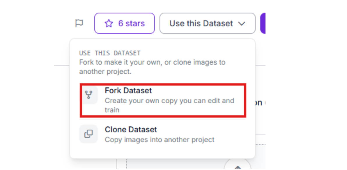
Visit Roboflow Universe and search for "Car Dents." Click "Fork Project" to import these images into your own workspace so you can customize the training.
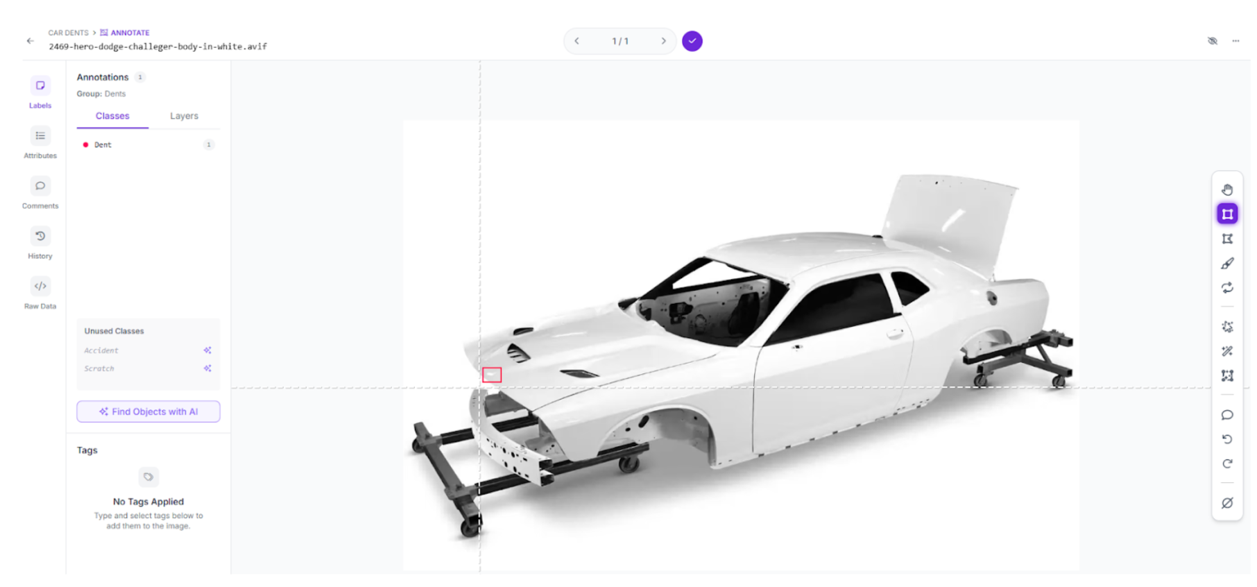
Step 3: Labeling and Annotation
If you have captured your own BiW images, use Roboflow’s annotation tools to label them. If you are using a forked dataset, you can add "Negative" images (clean metal) to help the model reduce false positives.
Step 4: Train the RF-DETR Object Detection Model
We will train an RF-DETR model. This transformer-based architecture is the first real-time model to break the 60 mAP barrier, making it ideal for the precision required in automotive safety.
- Start Custom Training: Navigate to the "Train" tab
- Select your preferred model architecture:
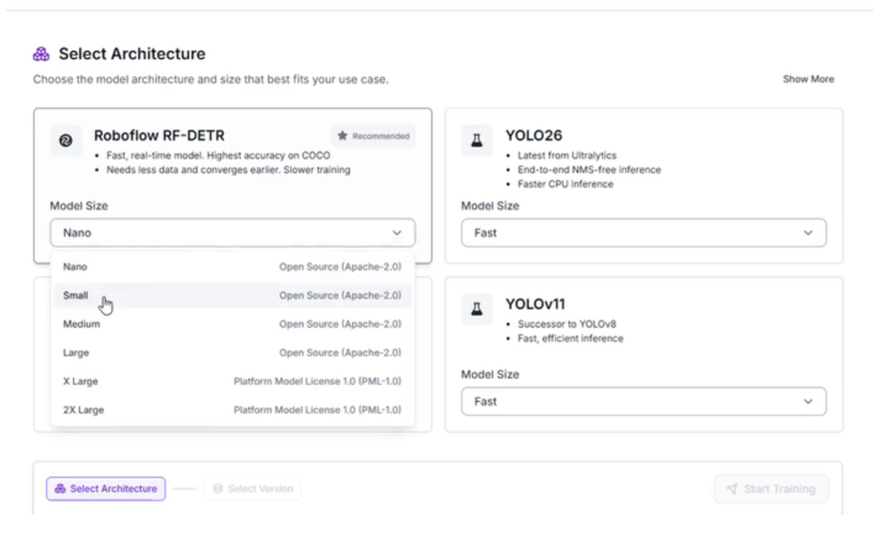
Why We Chose RF-DETR Small
For this Body-in-White inspection system, we are selecting RF-DETR Small. While the larger models offer slightly higher precision, the "Small" variant is the optimal choice for this specific workflow for several reasons:
- High-Speed Inference: In automotive manufacturing, the assembly line moves quickly. RF-DETR Small provides the low latency required to inspect panels in milliseconds without causing a bottleneck in production.
- Edge Compatibility: Because we want to run this inspection locally on the factory floor using devices like an NVIDIA Jetson, the Small architecture ensures the model fits within the memory constraints of edge hardware while maintaining peak performance.
- The Reasoning Guardrail: Since we are using a Vision Agent (Gemini 3.1 Pro) as our second stage, the RF-DETR model doesn't need to be 100% perfect on its own. Its primary job is to act as a high-speed "triage" system that identifies areas of interest, leaving the heavy-duty reasoning to the AI layer.
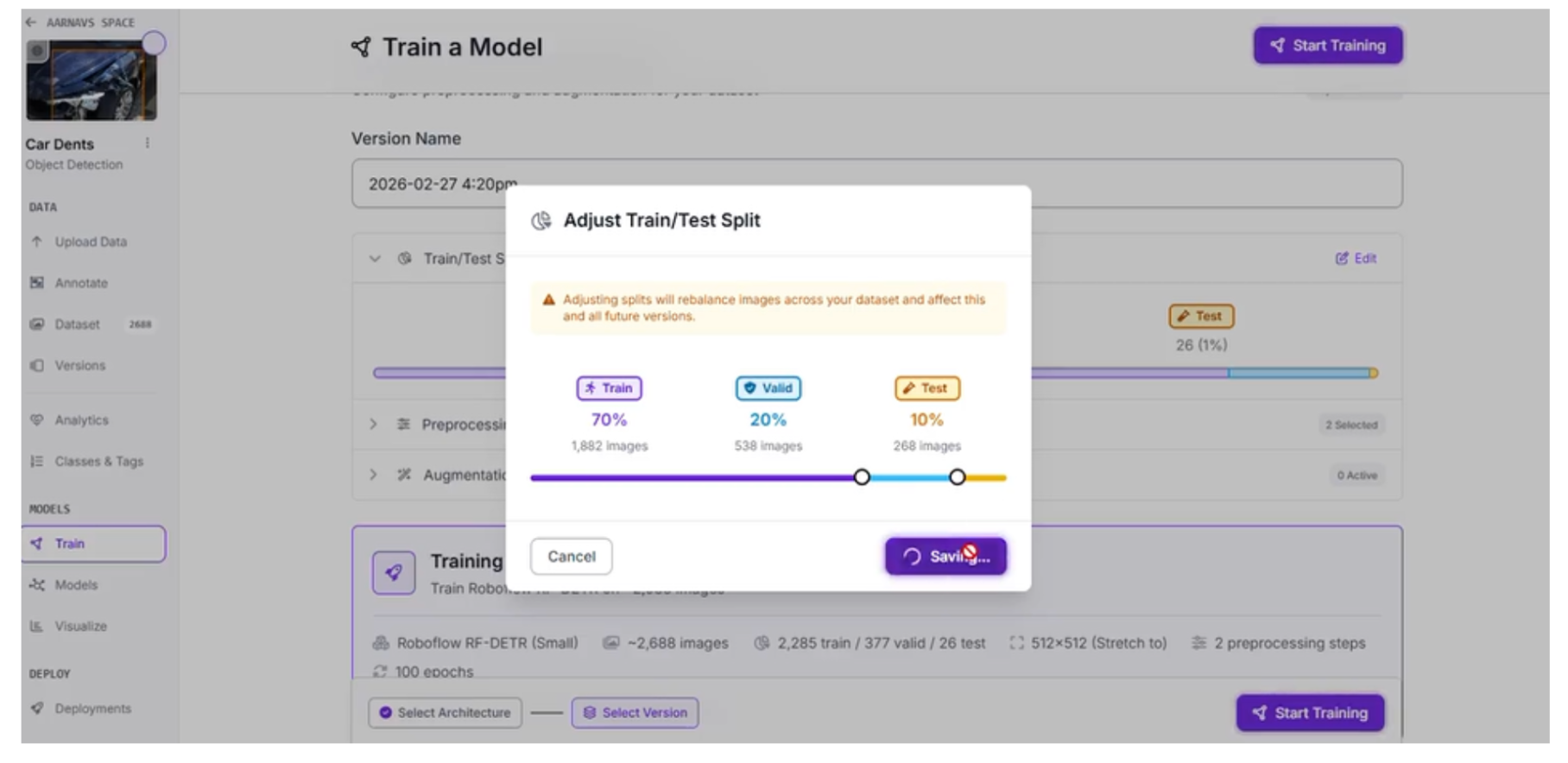
Step 5: Configure your “Train/Test split”
When preparing your automotive dataset, the way you divide your images is as important as the quality of the labels themselves. For this BiW inspection system, we are using a 70/20/10 split: 70% for Training, 20% for Validation, and 10% for Testing.
Why the 70/20/10 Split?
This specific ratio is a standard best practice in machine learning for several reasons:
10% Testing (The Final Grade): These images are held back and never seen by the model during training. This provides an unbiased evaluation of how the system will perform on a real factory floor when it encounters a car panel it has never seen before.
20% Validation (The Practice Exam): This portion is used during the training process itself. The model periodically checks its work against this set to tune its hyperparameters. This helps prevent overfitting, ensuring the model doesn't just memorize your specific images but actually learns to identify the concept of a dent.
70% Training (The Learning Phase): The bulk of your data is dedicated to the model's "education." This provides the RF-DETR Small model with enough examples of various metal textures, dent sizes, and lighting conditions to recognize patterns effectively.
Step 6: Apply Preprocessing and Augmentations
To ensure our system is resilient to the chaotic environment of a high-speed production line, we need to prepare the data to handle real-world variables. We applied specific preprocessing and augmentation steps to make the model "hardware agnostic." This ensures that whether the camera is mounted slightly off-angle or the factory lighting flickers, the model still performs accurately.
Here are the specific settings used for this BiW inspection task:
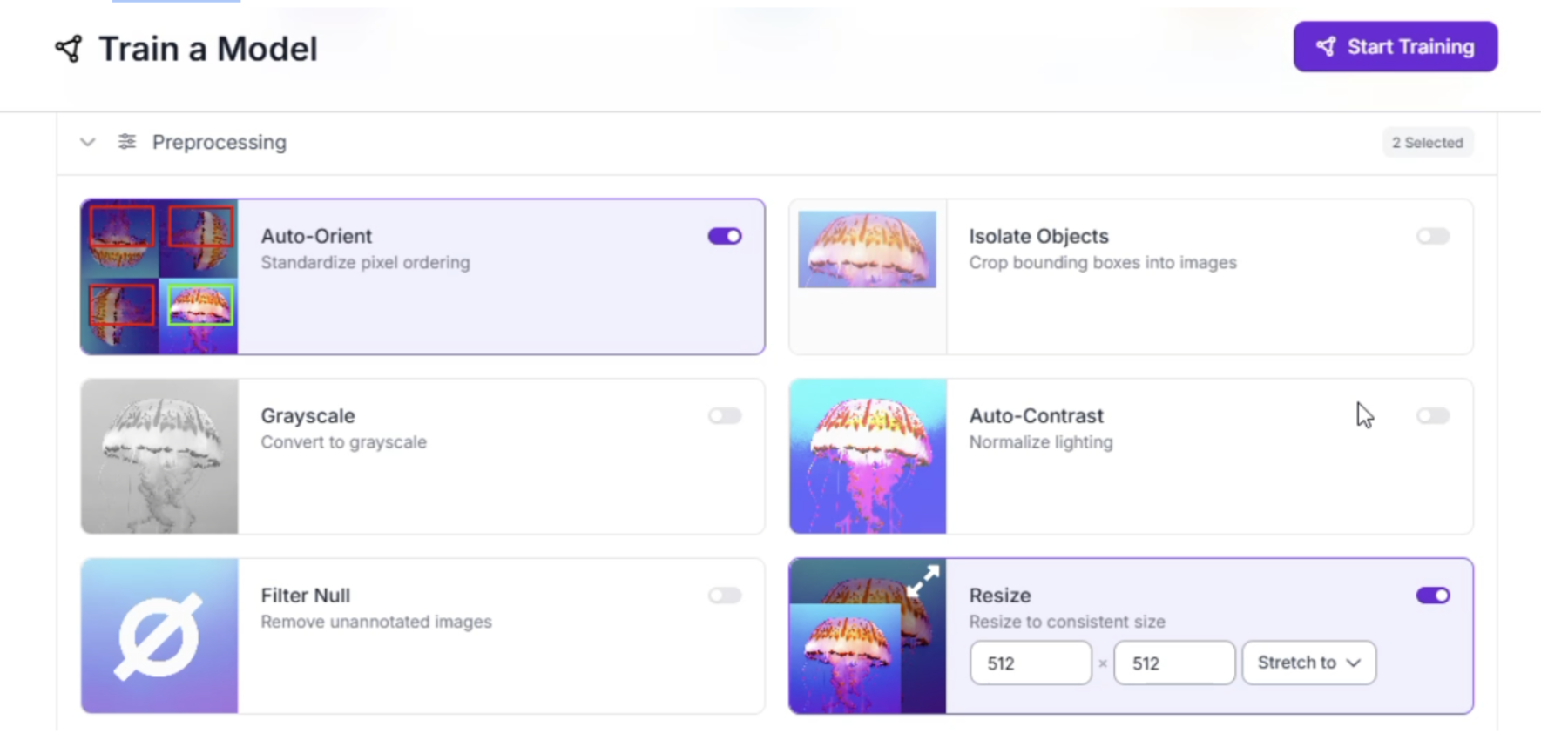
Preprocessing
Standardizing the images before they reach the model is vital for consistent inference speeds.
- Auto-Orient: Strips orientation metadata so the model doesn't get confused if a camera is mounted sideways or upside down on the line.
- Resize (Stretch to 512x512): We chose 512x512 to balance the need for fine-text detail on metal surfaces with the computational speed required for a real-time RF-DETR model.
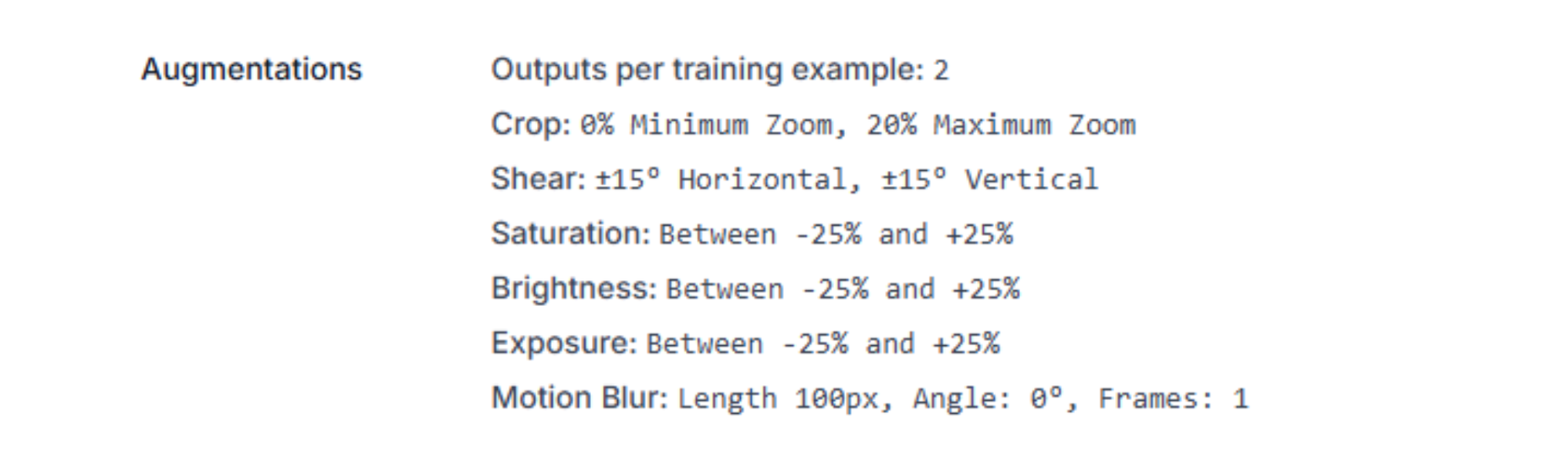
Augmentations (Outputs per training example: 2)
By generating two variations of every image, we artificially expand our dataset and teach the model to look past environmental "noise."
- Crop (0% Min, 20% Max Zoom): Simulates the vehicle chassis being at slightly different distances from the camera as it moves down the conveyor.
- Shear (±15° Horizontal/Vertical): Accounts for the camera not being perfectly perpendicular to the car panel, which is common in tight factory spaces.
- Saturation, Brightness, and Exposure (±25%): These three work together to simulate the extreme reflections and shadows found on raw Body-in-White metal.
- Motion Blur (100px): This is the most critical setting for automotive lines. It simulates the blur that occurs when a high-speed camera captures a moving chassis, ensuring the model can still "see" a dent even at high velocity.
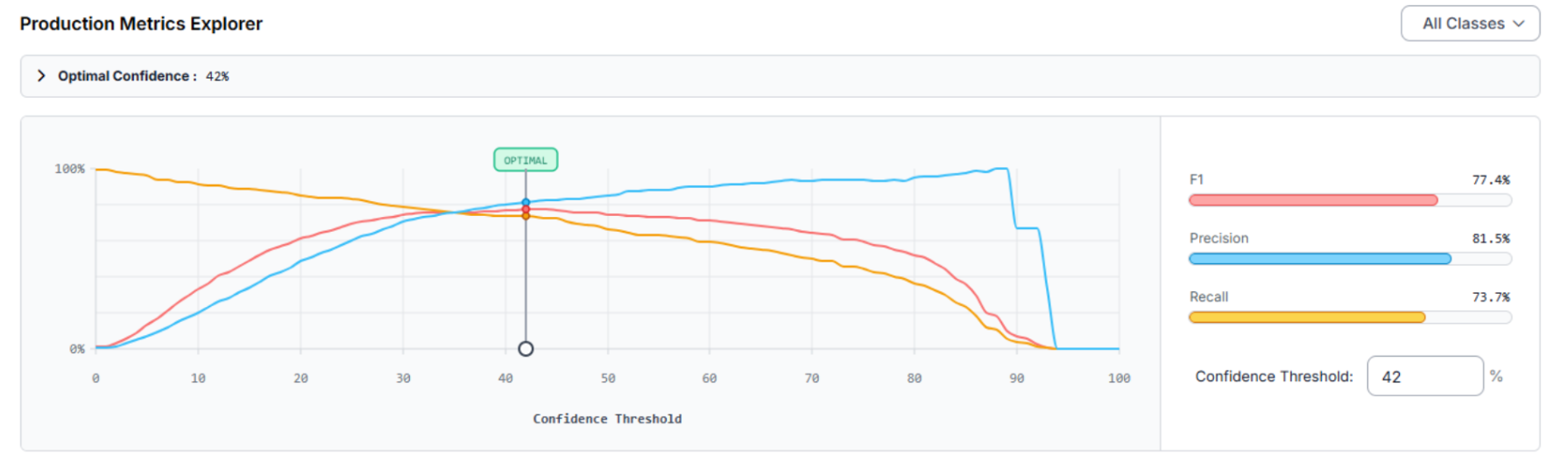
Step 7: Evaluate Model Results
Once training is complete, we use the Production Metrics Explorer to transition from a raw model to a factory-ready system. The goal is to find the Optimal Confidence Threshold, the point where the model is most accurate across all classes, by balancing precision and recall.
Analyzing the Production Metrics
For our BiW inspection system, the explorer identified an Optimal Confidence of 42%, achieving an F1 Score of 77.4%.
Recall (73.7%): The model successfully captures 73.7% of all actual defects present in the test set.
Precision (81.5%): When the model flags a "Dent," it is correct 81.5% of the time, reducing "ghost" stops on the assembly line.
Model Improvement Recommendations
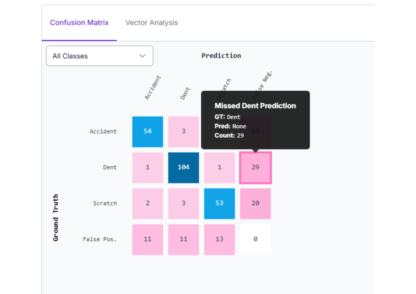
The metrics provide a clear roadmap for improving version 2.0 through the Confusion Matrix:
Reduce False Negatives: With 29 missed detections, the "Dent" class is frequently overlooked. We can fix this by adding more BiW-specific images to the training set.
Small Object Detection: If defects are microscopic, we can implement Tiling or use a larger model architecture to improve resolution for tiny imperfections.
Differentiate "Scratch" vs. "Dent": The model occasionally misclassifies scratches as dents. Improving label quality and adding varied examples of both will help the model learn the unique shadow gradients of each.
Step 8: Create the Vision Agent Workflow
Training the model is only the first half. To automate the "reasoning," we will build a Roboflow Workflow. Here’s the one that was made in this article.
1. Initialize the Workflow
Start by setting up the logic environment within Roboflow Workflows. Navigate to the Workflows tab on the left sidebar.
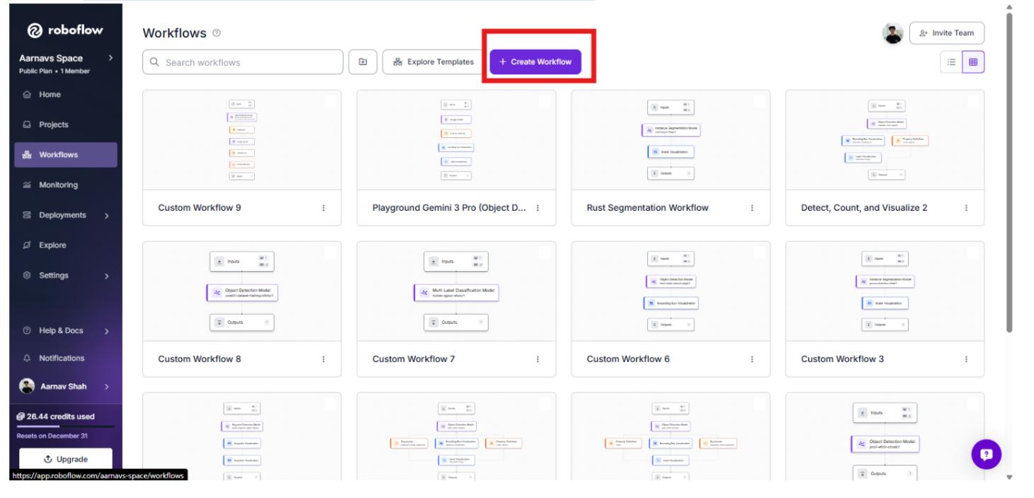
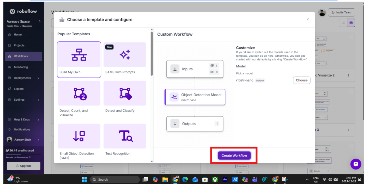
Click "Create Workflow" and select "Build Your Own" to begin with a clean canvas.
2. Add the Perception Layer: RF-DETR
The first block in our BiW pipeline is the Object Detection block.
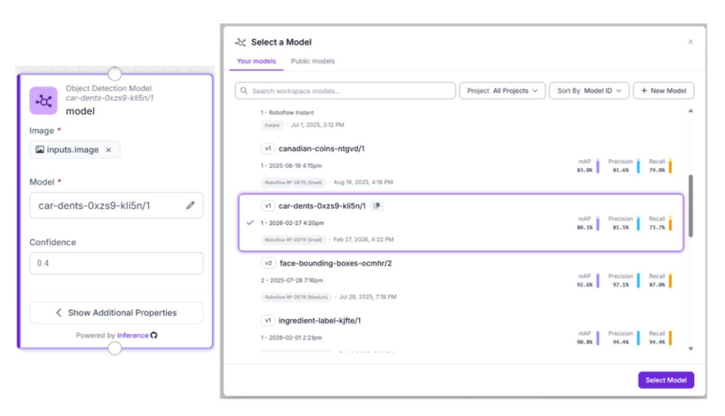
- Model Selection: Use your custom RF-DETR model (ID: car-dents-0xzs9-kli5n/1).
- The Logic: This block acts as the high-speed "eyes" of the system. It scans every chassis passing through the quality gate, filtering out perfect panels and highlighting areas of interest.
3. Gate the Workflow with "Continue If" logic
To keep the system lean and cost-effective, add a Continue If block. This acts as a smart filter, ensuring the AI "Brain" only activates when a human-level inspection is truly necessary.

- Configure Condition: Based on our workflow code, we set a logic gate where the system proceeds if the confidence of a detection falls below 80%.
- The Benefit: If the perception layer is absolutely certain that the panel is perfect, the workflow stops. If there is any doubt or a potential dent is detected, the image is passed to the next stage for deeper reasoning.
4. Add the Reasoning Layer: Gemini 3.1 Pro
When a potential anomaly is detected, the workflow passes the image to the Google Gemini block. This serves as the "Inspector," analyzing visual textures to distinguish between designed contours and production defects.
- Model: Select Gemini 3.1 Pro.
- Task Type: Structured Answering.
- Thinking Level: Depends on the scale of your workflow. For something simple like this, I chose “low”.
- Output Structure:
{
  "dent_detected": "Boolean. Set to true if a localized surface depression, crease, or impact mark is visible on the raw metal. Set to false if the panel surface is uniform and smooth.",
  "severity": "Categorize as 'High' for structural warping or dents >2cm, 'Medium' for visible surface 'dings', or 'Low' for microscopic scuffs or 'orange peel' textures on the unpainted surface.",
  "action_required": "Prescriptive instruction. If 'High', output 'IMMEDIATE LINE STOP'. If 'Medium', output 'MANUAL INSPECTION AT QUALITY GATE'. If 'Low', output 'LOG FOR TREND ANALYSIS'.",
  "logic": "Technical justification. Explain the visual evidence used to distinguish an actual defect from a designed stamping contour or a harmless light reflection on the reflective BiW panel."
}
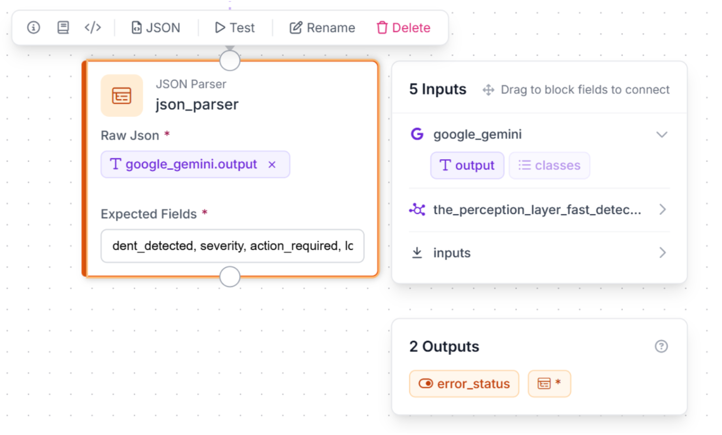
5. Structured Data
To turn AI reasoning into readable, factory-floor action, we use a JSON Parser block.
- JSON Parser: This block, named json_parser, takes Gemini’s raw output and transforms it into machine-readable fields: dent_detected, severity, action_required, and logic.
6: Test, Activate, and Iterate
Use the "Run Preview" button to validate the logic. You can test the system's ability to distinguish between a safe, designed contour and a real production-line dent.
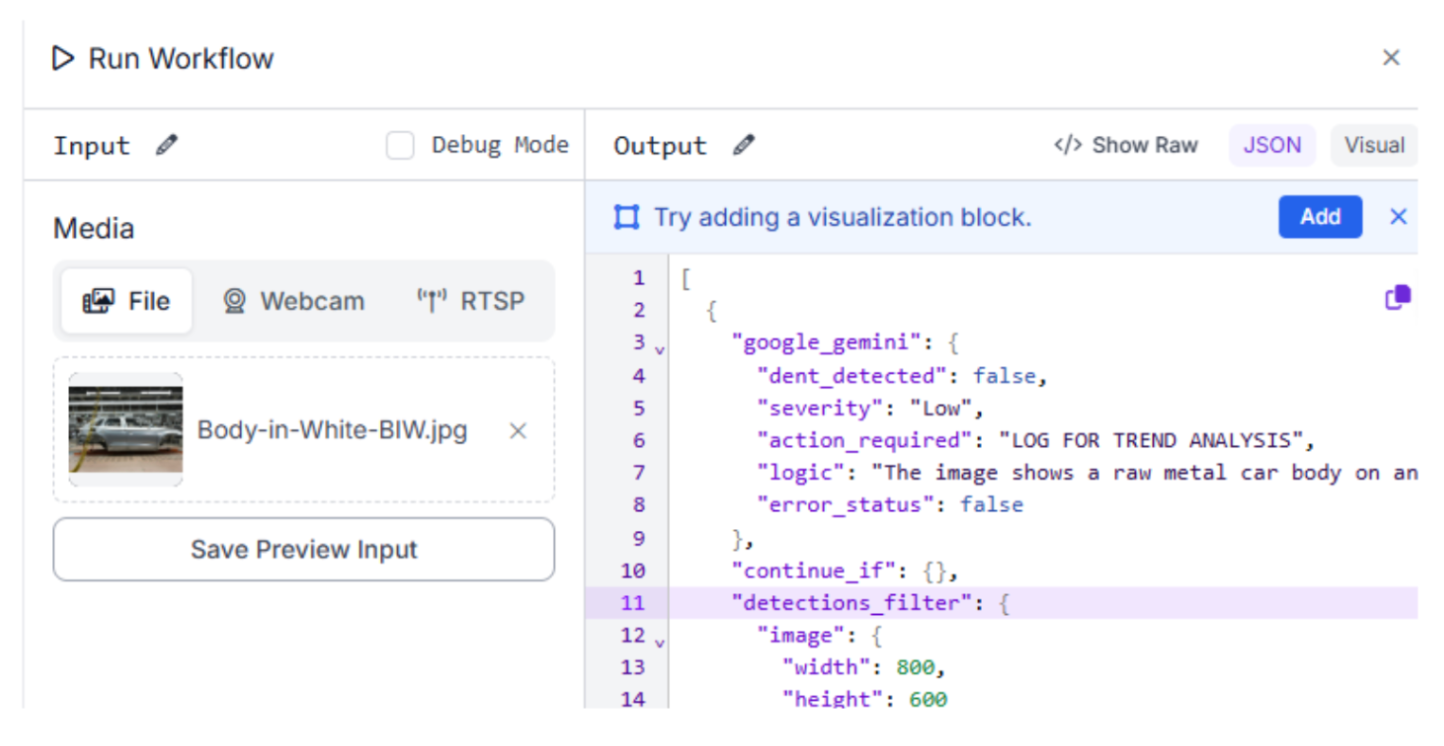
Output for test image:
"google_gemini": {
      "dent_detected": false,
      "severity": "Low",
      "action_required": "LOG FOR TREND ANALYSIS",
      "logic": "The image shows a raw metal car body on an assembly line. The visible surfaces appear uniform and smooth without any obvious localized surface depressions, creases, or impact marks. The contours visible are consistent with designed stamping lines and normal light reflections on the unpainted metal surface.",
      "error_status": false
Conclusion: Body-in-White Inspection System with Computer Vision
Preventing automotive defects is about leveraging the latest in AI to ensure every structure is perfect. By combining a generalized dent detection model with a high-level reasoning agent, you can create a robust inspection system tailored to the assembly line.
Ready to start building? Sign up for a free Roboflow account and explore automotive datasets on Universe today.
Written by Aarnav Shah
Cite this Post
Use the following entry to cite this post in your research:
Contributing Writer. (Mar 6, 2026). Build a Body-in-White Inspection System with Computer Vision. Roboflow Blog: https://blog.roboflow.com/body-in-white-inspection-system/