

Computer vision automates paint defect inspection by using an RF-DETR object detection model to accurately locate and classify surface imperfections like scratches, bubbling, and orange peel. By integrating this model into Roboflow Workflows, manufacturers can easily deploy a scalable pipeline that automatically labels and counts defects to streamline quality control.
Paint and protective coatings are widely used in industries such as automotive manufacturing, aerospace, construction, and consumer goods. In addition to improving appearance, these coatings can protect surfaces from moisture, corrosion, chemicals, and physical wear. For a coating to perform effectively, it must be applied evenly and remain free from defects.
Problems during surface preparation, paint application, or curing can produce visible imperfections such as scratches, bubbles, craters, and uneven textures. These defects may reduce the quality of the final product, weaken the coating, and expose the underlying material to damage. Detecting them early is therefore an important part of manufacturing quality control.
However, manually inspecting painted surfaces can be slow and subjective, particularly when production lines process large numbers of parts. Some defects are also small or visually similar, making consistent inspection difficult.
Computer vision can help automate this process by analyzing images of painted surfaces and locating visible defects. In this guide, we will train an object detection model using Roboflow and build a Workflow that identifies, labels, and counts paint defects in an image.
What Are Paint Defects?
Paint defects are unwanted irregularities that affect the appearance, structure, or protective performance of a painted surface. They may form before, during, or after the paint is applied.
Common causes include:
- Dirt, oil, moisture, or silicone on the surface
- Incorrect paint viscosity or mixing
- Uneven or excessive paint application
- Incorrect spray equipment settings
- Insufficient drying time between coats
- Incompatible paint layers
- Improper temperature or humidity during application
- Solvent or air trapped beneath the coating
- Physical damage after the paint has dried
Paint defects can range from minor cosmetic imperfections to failures that cause the coating to separate from the underlying material. Industrial inspections must therefore identify both the presence and type of each defect.
Types of Paint Defects
The dataset used in this guide contains 12 types of paint defects:
Scratch: A narrow mark or groove created when the painted surface is scraped or damaged. Scratches can affect only the topcoat or penetrate multiple coating layers, potentially exposing the material underneath.
Dirt: Dust, fibres, or other particles that become trapped in or settle on the paint. Dirt defects usually appear as small raised spots and are commonly caused by insufficient surface cleaning or contamination in the painting environment.
Bleeding: Unwanted discoloration that occurs when pigment or another substance from an underlying layer dissolves into and becomes visible through the new coating.
Bubbling: Raised circular areas that form when air, moisture, or solvent becomes trapped beneath or within the coating. These bubbles may weaken adhesion and eventually cause the paint to separate.
Cissing: Small circular depressions or exposed spots that form when wet paint pulls away from parts of the surface instead of spreading evenly. Cissing is often associated with contaminants such as oil, grease, or silicone.
Cratering: Bowl-shaped depressions in the coating that can form when trapped air escapes from wet paint or when surface contamination prevents the paint from flowing evenly.
Orange Peel: An uneven, bumpy texture that resembles the surface of an orange. It can develop when paint droplets do not flow together into a smooth film due to factors such as paint viscosity, temperature, solvent evaporation, or incorrect spray settings.
Peel-Off: The separation of the coating from the surface or an underlying paint layer. It may be caused by contamination, moisture, incompatible layers, or inadequate surface preparation.
Runs and Sags: Thick lines, drips, or curtain-like areas that form when wet paint flows downward before drying. Common causes include applying too much paint, using paint that is too thin, or holding the spray equipment too close to the surface.
Solvent Pop: Small holes or pinholes that form when trapped solvent rapidly escapes through a coating that has started to dry. It is commonly associated with overly thick coats or insufficient drying time.
Water Spotting: Circular marks or discoloured patches left when water droplets dry on a painted surface. Minerals or other substances contained in the water may remain behind and affect the coating’s appearance.
Wrinkle: A rough surface containing folds, ridges, or creases. Wrinkling can occur when the outer surface dries before the paint underneath, the coating is applied too thickly, or incompatible layers react with one another.
How to Build a Paint Defect Detection System
For this tutorial, we will build a computer vision system that detects visible defects on painted surfaces. We will use a public dataset from Roboflow Universe, train a custom Roboflow RF-DETR object detection model, and connect the model to a Roboflow Workflow.
The completed Workflow will locate each defect, draw a labelled bounding box around it, count the total number of detections, and display that count on the output image.
Step 1: Log in to Roboflow
Sign in to your Roboflow account to get started. If you do not have an account, you can create one for free. Once you are signed in, make sure you have a workspace set up. This is where the dataset, trained model, and Workflow will be stored throughout the project.

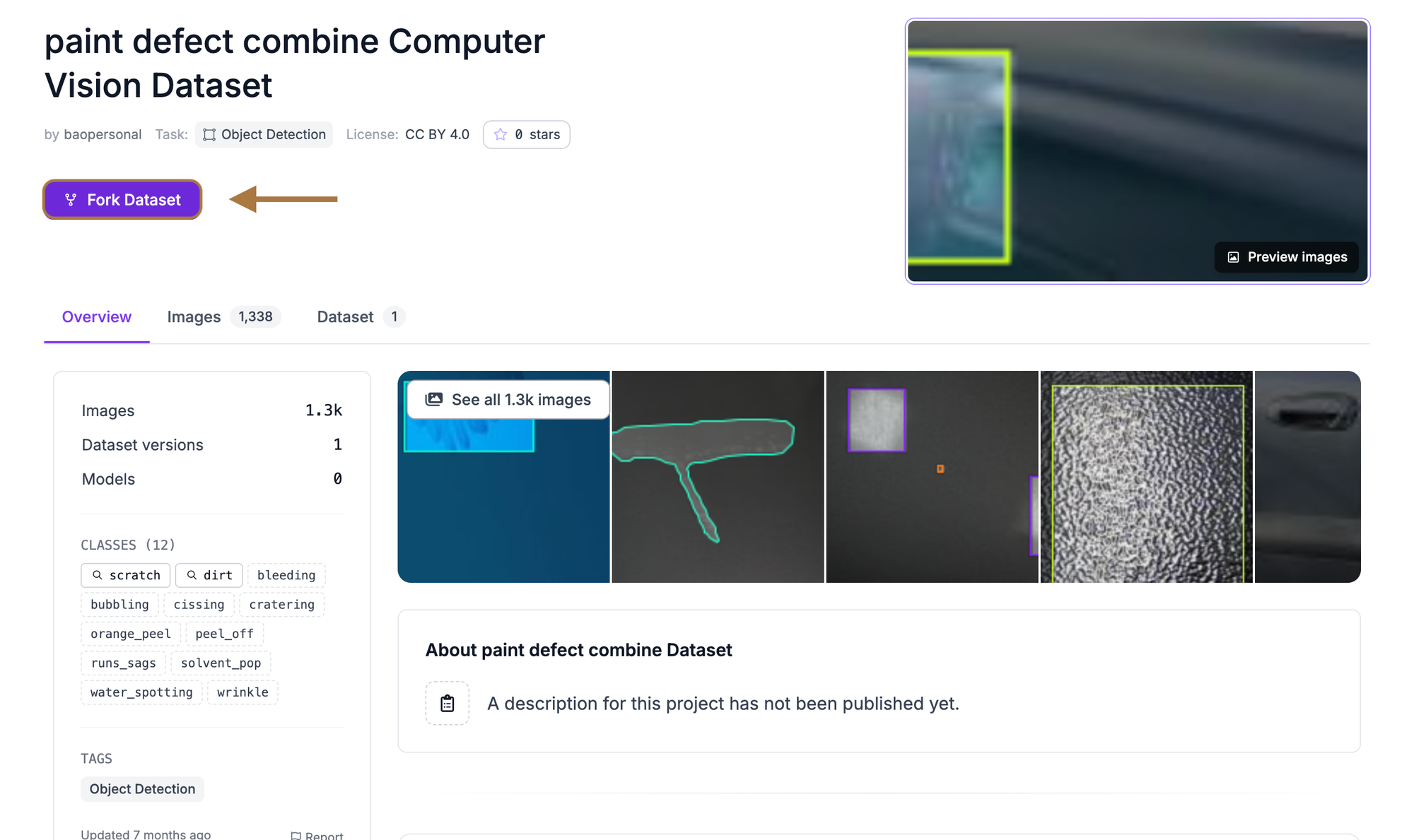
Step 2: Fork the Paint Defect Dataset
Rather than collecting and annotating paint defect images from scratch, we will use an existing open-source dataset from Roboflow Universe.
The Paint Defect Combine dataset contains 1,338 images annotated for object detection across the 12 paint-defect classes described above.
Forking the dataset creates a copy in your workspace. You can then generate your own dataset version and apply preprocessing and augmentation without changing the original project.
Open the dataset in Roboflow Universe and click Fork Dataset in the top-right corner. Select your workspace as the destination, then click Fork Dataset again to confirm. Roboflow will copy the images and annotations into a new project in your workspace.
Step 3: Train an RF-DETR Model
After forking the dataset, open the project and click the Train button. Select Custom Training as the training engine.
When prompted to choose a model architecture, select RF-DETR and set the model size to Small. RF-DETR is an object detection architecture that can identify multiple defects in an image and return a bounding box, class name, and confidence score for each detection.
Before training can begin, Roboflow will guide you through configuring the dataset split, preprocessing, and augmentation.
Step 4: Configure the Dataset Split
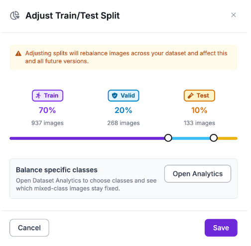
Before training the model, divide the images into training, validation, and test sets.
The training set contains the images from which the model learns. The validation set is used during training to measure improvement and identify possible overfitting. The test set remains separate until training is complete and is used to evaluate the final model.
When generating the dataset version, review the existing split and adjust it if necessary. A common split is:
- 70% training
- 20% validation
- 10% testing
Roboflow will automatically assign the images to each set based on the selected percentages.
Step 5: Apply Preprocessing and Augmentation
Next, apply preprocessing and augmentation to the dataset. Preprocessing creates a consistent input format, while augmentation generates realistic variations of the training images to help the model generalize to new conditions.
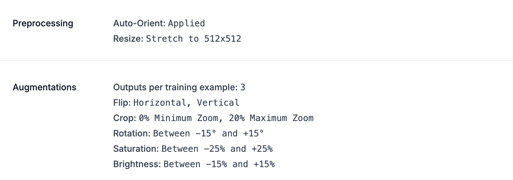
For preprocessing, apply the following:
- Auto-Orient: Corrects image orientation using the image’s stored metadata.
- Resize: Stretches each image to 512 × 512 pixels, giving the model a consistent input size.
For augmentation, set the output per training example to 3. This creates two augmented versions for each original training image.
Apply the following augmentations:
- Horizontal Flip: Helps the model recognize defects when surfaces appear in different horizontal orientations.
- Vertical Flip: Accounts for painted parts being photographed from different directions.
- Rotation: Set between -15° and +15° to simulate small changes in camera alignment.
- Crop: Set between 0% minimum zoom and 20% maximum zoom to vary the position and apparent size of defects.
- Brightness: Set between -15% and +15% to account for different lighting conditions.
- Saturation: Set between -25% and +25% to account for moderate differences in paint colour and camera appearance.
These augmentations introduce useful variation while preserving the shapes and textures that distinguish the defect classes.
Once the settings are configured, click Generate to create the dataset version.
Step 6: Evaluate the Training Results
Once training is complete, Roboflow will evaluate the model using images from the test set. The trained paint-defect detection model achieved the following results:
| Metric | Score |
|---|---|
| mAP@50 | 67.2% |
| Precision | 66.5% |
| Recall | 68.0% |
| F1 | 67.2% |
The model achieved an mAP@50 of 67.2%, indicating moderate performance across the 12 paint-defect classes. The 66.5% precision score shows how reliably the model’s detections correspond to actual defects, while the 68.0% recall score measures its ability to find defects present in the test images. Finally, the 67.2% F1 score indicates that the model maintains a relatively even balance between precision and recall.
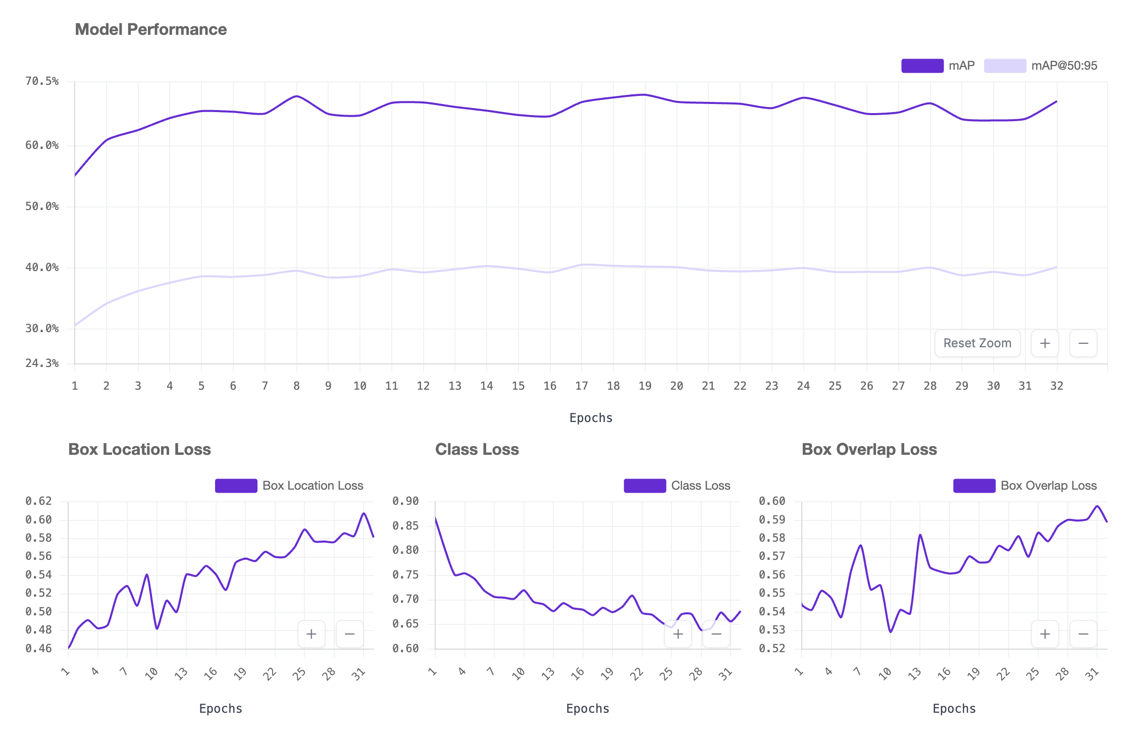
These results are sufficient for demonstrating how a paint-defect detection system can be built with Roboflow. However, a production system would require stronger and more thoroughly validated performance, particularly because missed or incorrectly classified defects could affect quality-control decisions. Performance could be improved by collecting more representative images, correcting inconsistent annotations, and adding examples of underperforming classes.
It is also important to review the per-class metrics and confusion matrix. Several paint defects, including bubbling, cissing, cratering, and solvent pop, share similar visual characteristics. As a result, the model may perform better on visually distinctive classes while having difficulty distinguishing between defects with similar textures and shapes.
Step 7: Build the Paint Defect Detection Workflow
Now that the model is trained, we can connect it to a Roboflow Workflow.
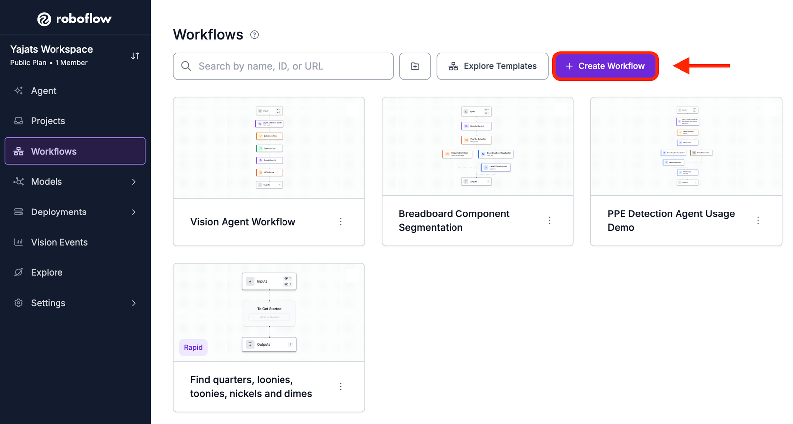
Navigate to the Workflows tab in your Roboflow dashboard and click Create Workflow. Start with a blank Workflow. The Input and Output blocks will already be included.
The completed Workflow contains the following blocks:
- Object Detection Model
- Property Definition
- Bounding Box Visualization
- Label Visualization
- Text Display
The Object Detection Model identifies defects in the input image. The Property Definition block counts the detections, while the visualization blocks draw and label their bounding boxes. Finally, the Text Display block places the total defect count on the resulting image.
The completed Workflow detects paint defects, draws labelled bounding boxes around them, counts the total number of detections, and displays the count on the output image. You can try the complete paint defect detection Workflow here.
Block 1: Object Detection Model
The first block is the Object Detection Model. It runs the trained RF-DETR model on the input image and returns the defects it detects.
Click Add Block and search for Object Detection Model. Connect it to the Image Input block. In its configuration panel, select your trained paint-defect model from the model dropdown.
Configure the image input to use the image provided by the Workflow’s Input block. You can also adjust the confidence threshold to control which predictions are returned. Predictions below the selected confidence threshold will be removed.
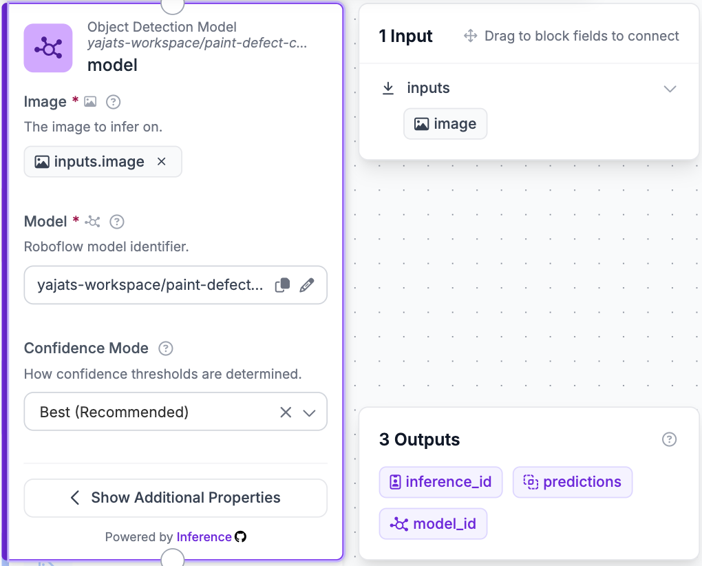
Each returned prediction includes:
- Bounding-box coordinates
- Predicted defect class
- Confidence score
Because an image can contain multiple paint defects, the block may return several predictions for a single image.
Block 2: Property Definition
Next, add a Property Definition block. This block extracts a property from the model’s predictions. In this Workflow, it is used to calculate the total number of detected defects.
Connect the Property Definition block to the Object Detection Model and configure it as follows:
- Data: Select the predictions returned by the Object Detection Model.
- Operation: Select Count Items.
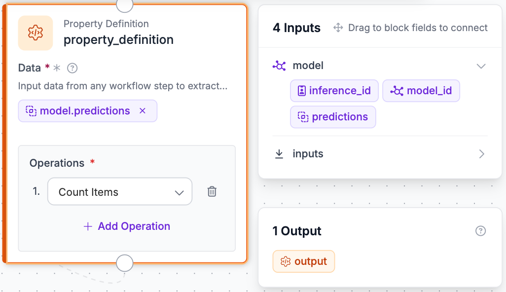
The resulting value represents the number of paint-defect detections in the image. For example, if the model detects two scratches and one water spot, the block will return a total count of three.
This count does not determine whether the surface passes or fails. Instead, it provides a simple numerical summary of the model’s detections.
Block 3: Bounding Box Visualization
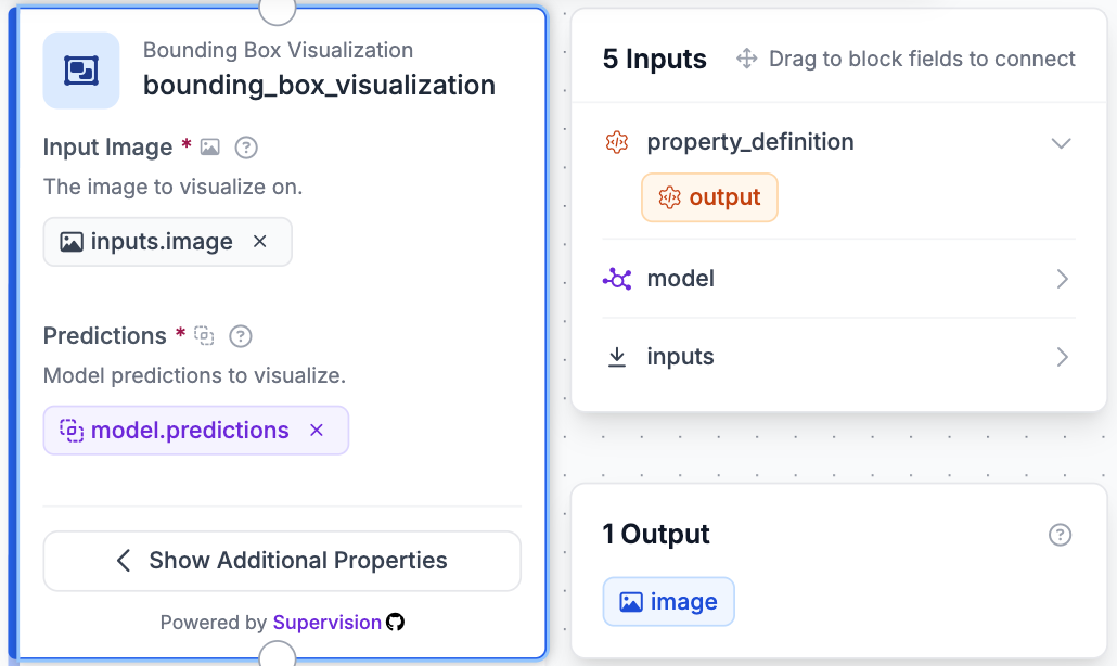
Add a Bounding Box Visualization block after the Property Definition block. This block draws a box around each defect detected by the model.
Configure it using:
- Image: Select the original input image.
- Predictions: Select the predictions from the Object Detection Model.
The box positions and sizes are taken from the coordinates returned by the model. This allows someone reviewing the result to see exactly where each defect was detected.
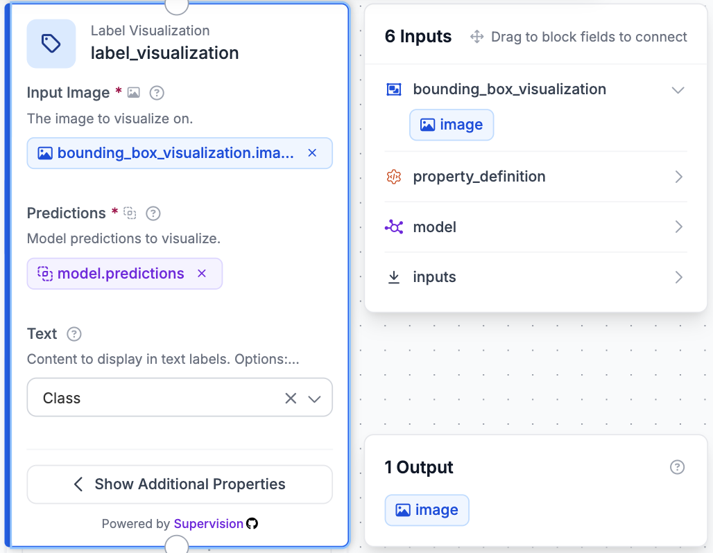
Block 4: Label Visualization
Next, add a Label Visualization block. Connect it after the Bounding Box Visualization block so the labels are drawn on top of the image that already contains the bounding boxes.
Configure the block using:
- Image: Select the output image from Bounding Box Visualization.
- Predictions: Select the predictions from the Object Detection Model.
Set the displayed text to include the class name. Each bounding box will then show the predicted defect type, such as scratch, orange_peel, or water_spotting.
Block 5: Text Display
The final processing block is Text Display. This block overlays the total defect count on the annotated image.
Connect the Text Display block after Label Visualization. Use the output from the Label Visualization block as its input image.
Set the displayed text to:
Total Defects: {{ $parameters.total_defects }}In the text parameters, reference the count returned by the Property Definition block:
{
  "total_defects": "$steps.property_definition.output"
}
The precise output property shown by Roboflow may vary based on how the Property Definition block is configured.
Set the position mode to relative and choose a location where the text remains visible without covering important detections.
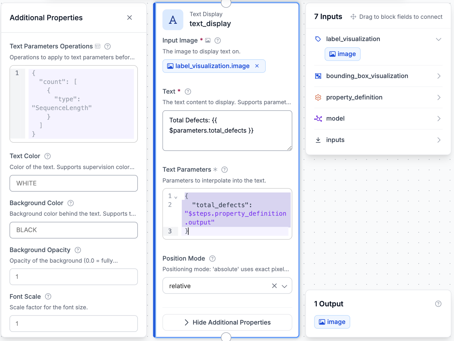
Finally, configure the Workflow Output block to return the image produced by Text Display. Click Save Workflow once all the blocks have been connected.
Step 8: Test the Workflow
After saving the Workflow, click the Test button in the upper-right corner of the editor. Upload an image containing one or more visible paint defects and run the Workflow.
The final output should contain:
- A bounding box around each detected defect
- The predicted defect class
- The total number of detected defects
Review the results to confirm that the bounding boxes and labels appear correctly. If the model produces too many incorrect detections, increase the confidence threshold in the Object Detection Model block. If it misses visible defects, try lowering the threshold.
Test the Workflow using multiple images and defect classes before deployment. This will help determine whether the selected confidence threshold works consistently across different colours, surfaces, lighting conditions, and defect types.
Step 9: Deploy the Workflow
Once you are satisfied with the Workflow’s results, click Deploy in the upper-right corner of the editor. From the deployment options, select Cloud Hosted API.
Roboflow will generate code that can be used to run the Workflow from an application. First, install the Inference SDK:
pip install -U inference-sdkThen use the following Python code:
from inference_sdk import InferenceHTTPClient

client = InferenceHTTPClient(
    api_url="https://serverless.roboflow.com",
    api_key="YOUR_API_KEY"
)

result = client.run_workflow(
    workspace_name="YOUR_WORKSPACE",
    workflow_id="YOUR_WORKFLOW_ID",
    images={
        "image": "YOUR_IMAGE.jpg"
    },
    use_cache=True
)

print(result)
Replace YOUR_API_KEY, YOUR_WORKSPACE, YOUR_WORKFLOW_ID, and YOUR_IMAGE.jpg with your own values.
Running the script sends the selected image through the Workflow and returns the annotated output containing the detected paint defects and total count.
If you need to process sensitive manufacturing images locally, you can select a self-hosted deployment option instead. This allows inference to run on your own hardware rather than sending images to the cloud.
Paint Defect Detection System Conclusion
In this guide, we built a paint-defect detection system using Roboflow. We used an object detection dataset containing 12 types of paint defects, trained an RF-DETR model, and created a Workflow that identifies, labels, and counts defects on painted surfaces.
Although several defects can share similar visual characteristics, computer vision provides a scalable way to inspect painted products more consistently. The same system could be adapted for automotive panels, industrial equipment, consumer products, and other manufactured parts where coating quality is important.
By adding more representative training images and reviewing weak-performing classes, the model can be improved further for the lighting, materials, camera positions, and defects found in a specific production environment.
Further reading:


Cite this Post
Use the following entry to cite this post in your research:
Yajat Mittal. (Jul 10, 2026). How to Detect Paint Defects with Computer Vision. Roboflow Blog: https://blog.roboflow.com/detect-paint-defects-with-computer-vision/