

Dimensional defects are parts that fall outside their intended size, spacing, position, or alignment tolerances, invisible to the eye but enough to stop a part from fitting or working. You can catch them automatically in a Roboflow Workflow: Gemini detects the features, a small Python block measures the center-to-center distance, and it returns a pass or fail against your tolerance.
At first glance, a manufactured product may look perfectly fine. There are no scratches, dents, or other visible defects, and everything appears to have been made correctly. However, even a small difference in size, spacing, or alignment can be enough to prevent the product from functioning as intended.
These types of issues are known as dimensional defects. Unlike surface defects, which affect a product's appearance, dimensional defects occur when a part's size, spacing, or alignment falls outside its intended specifications. Even small measurement errors can impact product quality, assembly, and performance.
In this guide, we will explore what dimensional defects are, look at some common examples, and build a Roboflow Workflow that uses computer vision to automatically inspect parts for dimensional defects.
What Are Dimensional Defects?
A dimensional defect occurs when a manufactured part falls outside its intended dimensions or tolerances. Unlike surface defects, which affect a product's appearance, dimensional defects are related to a part's physical geometry, such as its size, spacing, position, or alignment.
For example, a part may be slightly too long, a hole may be drilled a few millimeters away from its intended position, or two components may be spaced farther apart than expected. While these differences can be small, they may prevent a product from fitting together correctly or functioning as intended.
Because of this, dimensional defect inspection plays an important role in manufacturing quality control, helping ensure that every part meets the required specifications before it reaches the customer.
Common Types of Dimensional Defects
Dimensional defects can appear in many different forms depending on the product being manufactured. Some of the most common examples include:
- Incorrect dimensions: A part is longer, shorter, wider, or taller than its intended size.
- Hole position errors: A hole is drilled slightly above, below, or beside its intended location.
- Incorrect spacing: The distance between two holes, connectors, or other features falls outside the acceptable tolerance.
- Misalignment: Components such as connectors, bottle caps, or other assembled parts are not positioned correctly.
- Excessive gaps: The gap between two parts is larger or smaller than expected, preventing a proper fit or seal.
Rather than manually inspecting every part, computer vision can automate much of this process by detecting the relevant features, measuring their dimensions or positions, and determining whether they fall within an acceptable tolerance. In the next section, we will build a Roboflow Workflow that performs this inspection automatically.
Build a Dimensional Defect Inspection Workflow
Now that we've explored what dimensional defects are and why they matter, let's build a Roboflow Workflow that automatically inspects the spacing between two mounting holes on a steel bracket. Here's the workflow we'll build.
Although this example focuses on measuring the distance between two holes, the same approach can be adapted to inspect many other dimensional features, including connector alignment, component spacing, hole position, gaps between assembled parts, or even the overall dimensions of a product.
Before getting started, it's important to understand one limitation of image-based measurements. Since our workflow measures distances directly from the image, every part should be captured under consistent conditions. Ideally, the camera should remain fixed with the same distance, angle, focal length, lighting, and image resolution throughout the inspection process. This ensures that measurements remain consistent from one image to the next.
In this tutorial, we'll compare measurements directly in pixels because every image is captured under identical conditions. If you're adapting this workflow for a real manufacturing application, begin by calibrating your camera using a known-good part or calibration target. This establishes the relationship between pixels and real-world units, allowing you to configure the expected dimensions and tolerances according to your product's specifications.
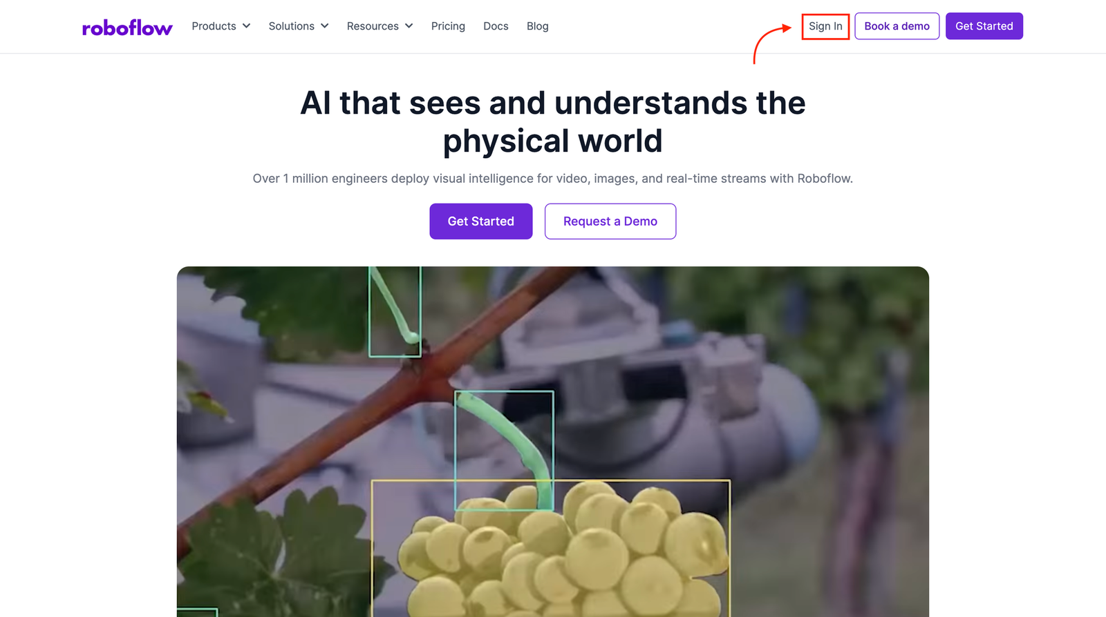
Step 1: Log into Roboflow
Start by logging into your Roboflow account. If you don't already have one, you can create a free account and access the Workflow editor from your dashboard.
Step 2: Create a Workflow
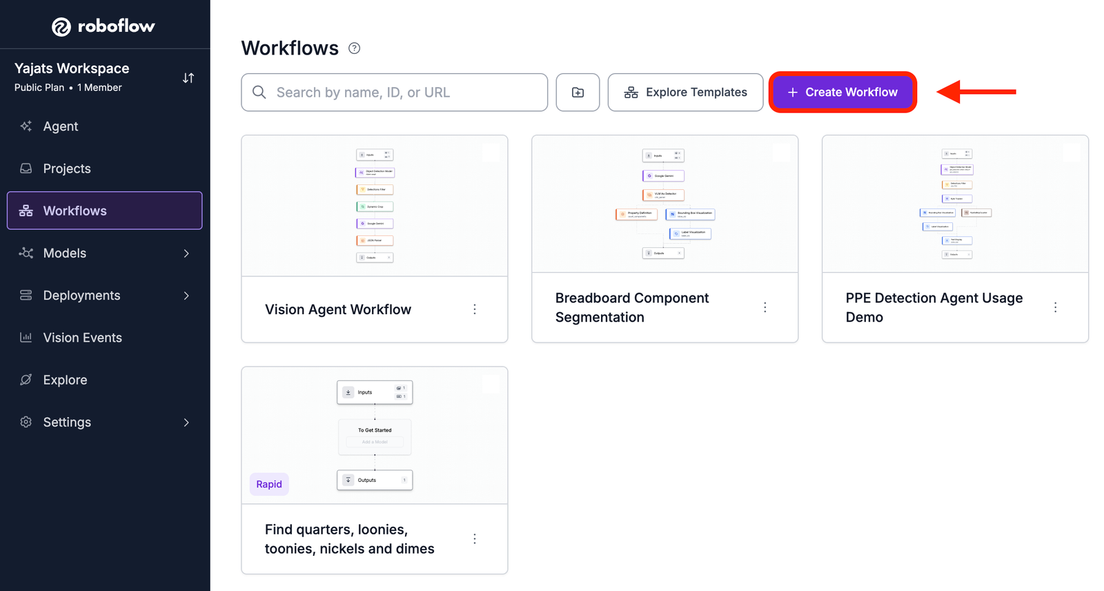
From the Roboflow dashboard, navigate to Workflows, then click Create Workflow.The Input and Output blocks are added automatically, so we'll focus on building the inspection pipeline between them.
Step 3: Add a Google Gemini Block
Add a Google Gemini block to the workflow and connect it to the inputs block. We'll use Gemini to detect the features we want to measure. Set Task Type to Unprompted Object Detection, then add three classes to the Classes field: mounting_bracket, left_hole, and right_hole. Including the bracket itself alongside the two holes provides Gemini with additional context, making it easier to localize two small, similar-looking holes accurately, rather than guessing at their position in isolation. Expand Additional Properties and set Model Version to Gemini 3.1 Pro, then set Thinking Level to low, since this is a straightforward detection task that doesn't need deep reasoning.
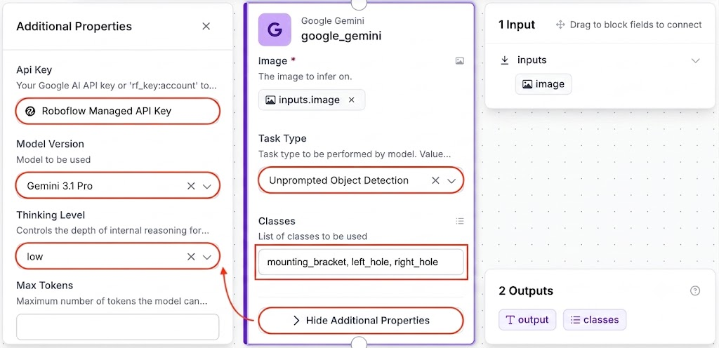
Once configured, Gemini returns predictions for the overall mounting bracket as well as each detected mounting hole. In the next step, we'll use the VLM As Detector block to convert these predictions into standard object detections with bounding boxes that can be processed by the remaining workflow blocks.
Step 4: Add a VLM As Detector Block
Add a VLM As Detector block and connect it to the Google Gemini block. Since Gemini's raw output is structured text rather than object detections, this block converts the response into standard bounding box detections.
Set Model Type to google-gemini and Task Type to Unprompted Object Detection.
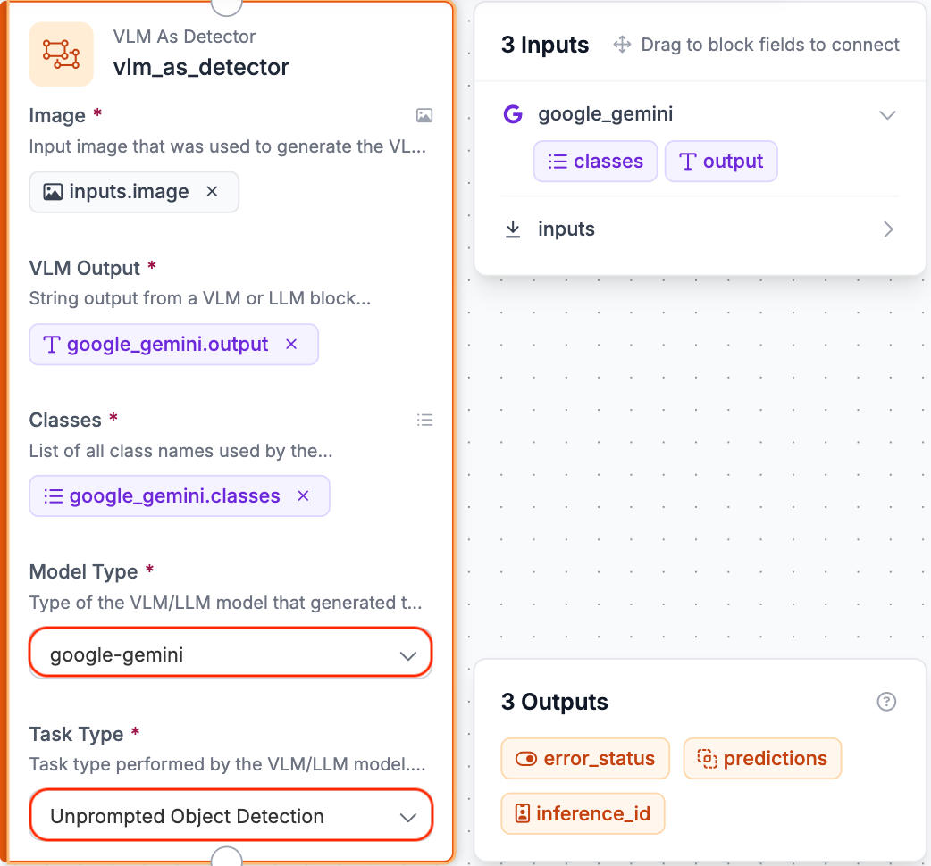
With this in place, the workflow now has proper bounding box detections for mounting_bracket, left_hole and right_hole that downstream blocks can actually measure against.
Step 5: Add a Custom Python Block
Now add a Custom Python Block. This is where the actual dimensional inspection happens. Click the Edit Code button and add three inputs in the panel that opens up. Add a predictions input and set type as object_detection_prediction. Then add two more inputs, expected_distance and tolerance, both typed as float/integer. Add two outputs as well, result typed as string and measured_distance typed as float, since the block needs to report both the pass/fail verdict and the number it measured.
import math

def run(self, predictions, expected_distance, tolerance):
    # Get class names from the detections
    class_names = predictions.data["class_name"]

    left_center = None
    right_center = None

    # Find the center of each detected hole
    for box, class_name in zip(predictions.xyxy, class_names):
        x_min, y_min, x_max, y_max = box

        center_x = (x_min + x_max) / 2
        center_y = (y_min + y_max) / 2

        if class_name == "left_hole":
            left_center = (center_x, center_y)

        if class_name == "right_hole":
            right_center = (center_x, center_y)

    # Stop if either hole was not detected
    if left_center is None or right_center is None:
        return {
            "result": "ERROR",
        }

    # Measure center-to-center distance
    dx = right_center[0] - left_center[0]
    dy = right_center[1] - left_center[1]
    measured_distance = math.sqrt(dx**2 + dy**2)

    # Compare measurement to tolerance
    if abs(measured_distance - expected_distance) <= tolerance:
        result = "PASS"
    else:
        result = "FAIL"

    return {
        "result": result,
        "measured_distance": measured_distance
    }
The script pulls the class name and bounding box for every detection, calculates the center point of whichever box is labeled left_hole and whichever is labeled right_hole, and if either one is missing it returns ERROR immediately rather than trying to measure a distance that doesn't exist. Once both centers are found, it measures the straight-line distance between them with the standard distance formula, then checks whether that measurement falls within tolerance of expected_distance. For this walkthrough, set expected_distance to 700 pixels and tolerance to 10 pixels, which are placeholder values you'll want to swap out for your own bracket's real spec once you're inspecting actual parts.
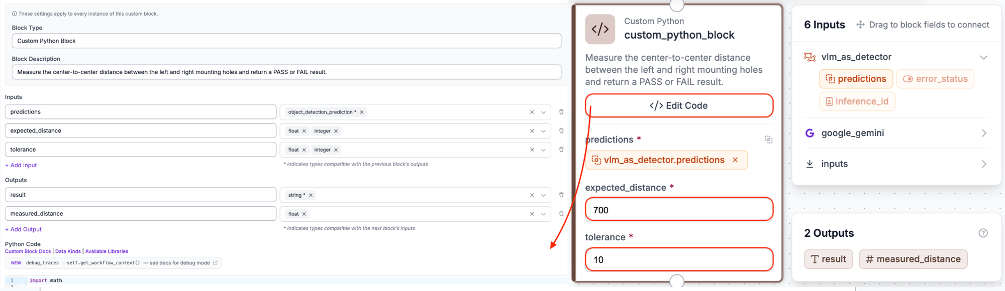
This is the step that actually turns two bounding boxes into a pass/fail decision, and because it's plain Python, you can adapt the measurement logic to check spacing, alignment, or any other geometric relationship without touching the rest of the pipeline.
Step 6: Add a Bounding Box Visualization Block
Add a Bounding Box Visualization block and connect it to the Custom Python Block. This draws a box around each detected hole and the mounting bracket directly on the output image, which is the first thing you'll want to check before trusting the measurement that comes out of the Python block.
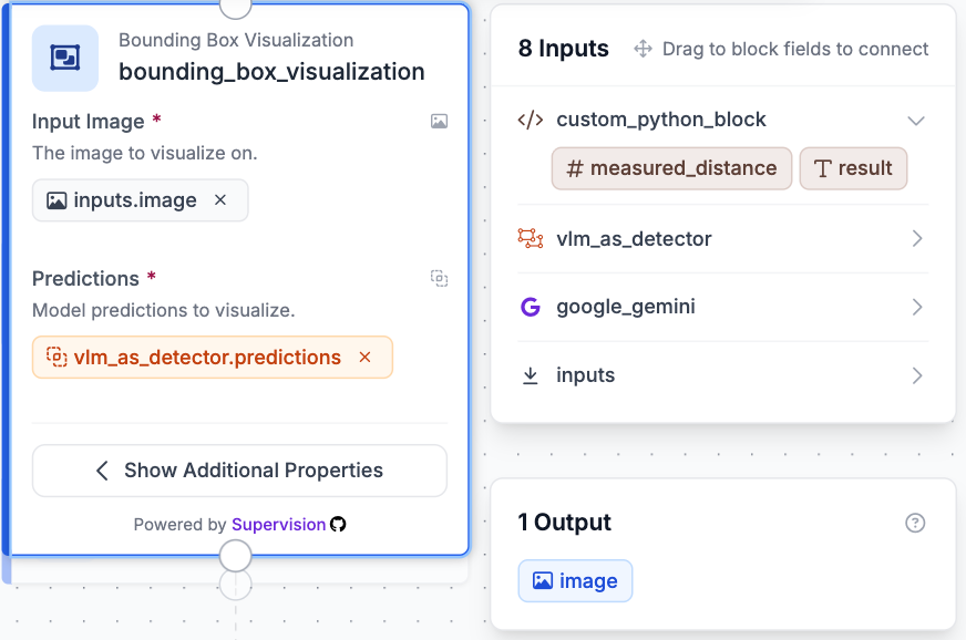
With the boxes drawn, you can immediately spot whether Gemini found both holes in roughly the right place, before you even look at the pass/fail result.
Step 7: Add a Label Visualization Block
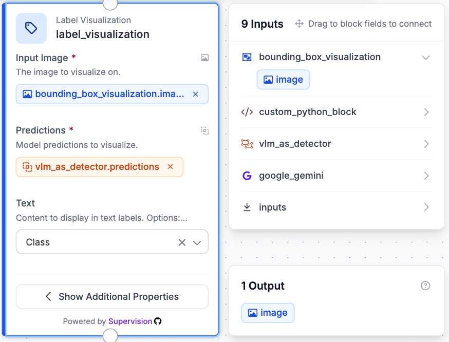
Add a Label Visualization block and connect it to the Bounding Box Visualization block. This overlays the class name for each detection, left_hole or right_hole, right next to its bounding box, so you can confirm at a glance that neither hole got mislabeled.
Step 8: Display the Inspection Result
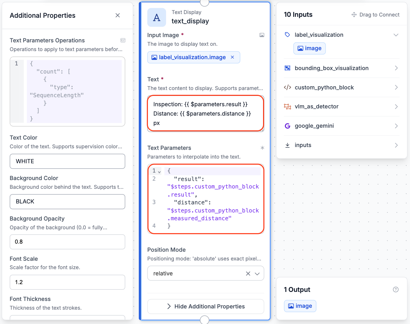
Add a Text Display block and connect it to the Label Visualization block, so the text gets overlaid on top of the already-annotated image. In the Text field, enter the following:
Inspection: {{ $parameters.result }}
Distance: {{ $parameters.distance }} px
Then fill in Text Parameters to map those template variables back to the Python block's outputs:
{
  "result": "$steps.custom_python_block.result",
  "distance": "$steps.custom_python_block.measured_distance"
}
Now the output image shows the annotated bracket, the pass/fail verdict, and the exact measured distance all in one place, so you don't have to cross-reference the raw JSON to see why a part failed.
Step 9: Test the Workflow
With every block connected, click the Test icon in the upper-right corner of the Workflow editor and upload a bracket image. Once the workflow finishes running, you'll see whether the part PASSES or FAILS inspection based on the measured hole spacing. The output will also display the measured center-to-center distance between the two mounting holes in pixels, allowing you to verify the measurement used to determine the inspection result.
Detect Dimensional Defects with Computer Vision Conclusion
In this blog, we explored what dimensional defects are, looked at several common examples, and built a Roboflow Workflow that automatically inspects the spacing between two mounting holes on a manufactured part. Using Google Gemini to detect the relevant features and a small Python block to perform the measurement, we created a simple dimensional inspection pipeline capable of determining whether a part falls within an acceptable tolerance.
While this example focused on hole spacing, the same workflow can be adapted to many other dimensional inspection tasks, including measuring gaps, verifying component alignment, checking connector positions, or validating overall part dimensions. By combining computer vision with automated measurement, manufacturers can perform consistent, repeatable inspections at scale while reducing the need for manual quality control.
Further reading:


Cite this Post
Use the following entry to cite this post in your research:
Yajat Mittal. (Jul 8, 2026). Dimensional Defect Inspection with Vision AI. Roboflow Blog: https://blog.roboflow.com/dimensional-defect-inspection-with-vision-ai/