
Inspecting buildings and bridges for cracks, ASR, and concrete degradation is hazardous and time-consuming when done manually, but a drone paired with a computer vision model can scan surfaces at close range and flag damage automatically. This tutorial covers collecting drone footage, annotating structural defects in Roboflow, training an object detection model, and querying it via a Python script that processes a live ESP32 CAM stream. The finished system correctly identifies cracks in walls in real time, producing output that could feed directly into a structural survey report.
Inspecting damage to structures such as houses and bridges can be an expensive, dangerous, and daunting process. To perform the required damage inspections, it is necessary that all its surface is seen and captured at close range.
It has already been proven that capturing close range footage with drones works in structural assessment, but there is a burning issue: how to filter through the footage to find damage without having to evaluate all images manually? That’s where computer vision comes in.
In this blog post, we’re going to talk through the process used to build a computer vision model to identify structural damage such as cracks, ASR, concrete degradation and more to any infrastructure like tall buildings, bridges, and houses.
Drone detection of cracks in the wall
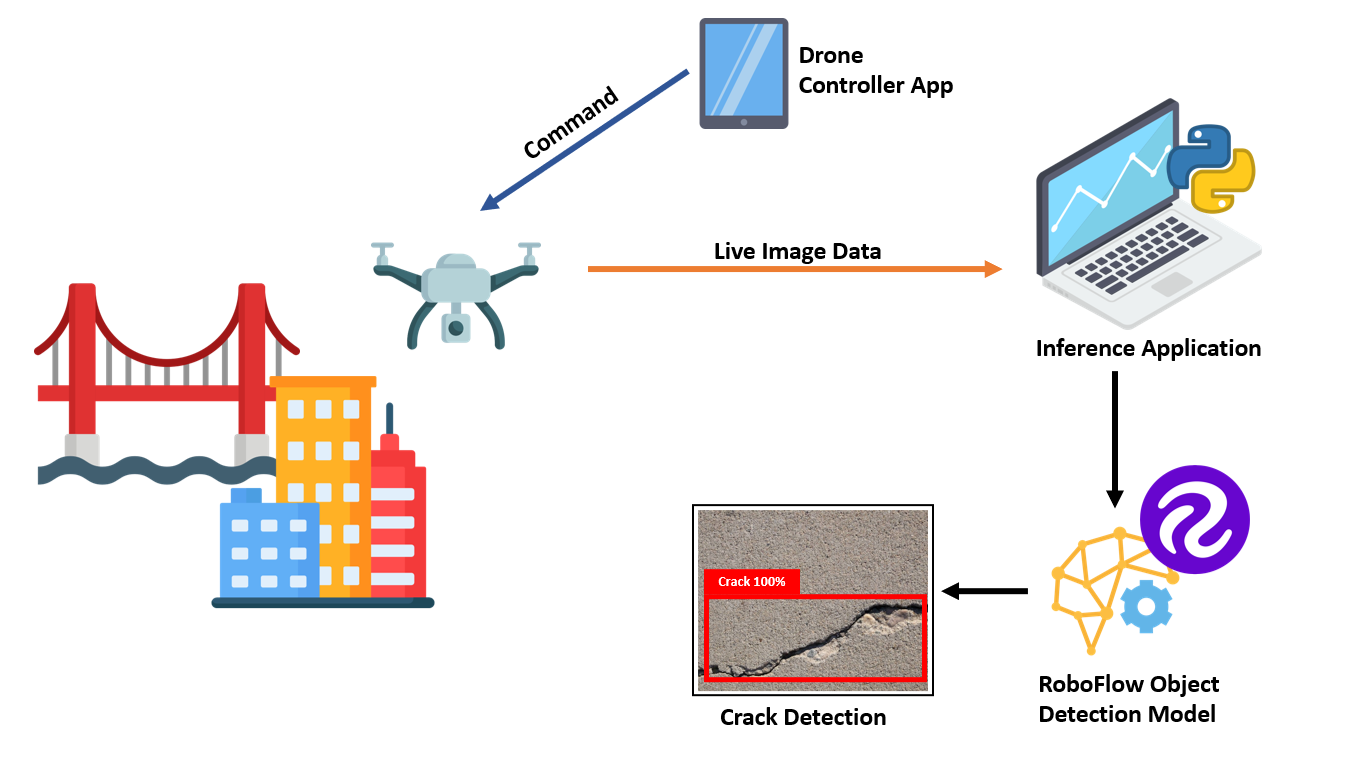
How the system works
In the system, a drone captures image data which is fed to the object detection model built using the Roboflow platform. This detection model can identify various types of structural damage. A simple Python script receives a live camera stream and runs the object detection model to detect the cracks. Below illustrates how the system works and how it is built and deployed.
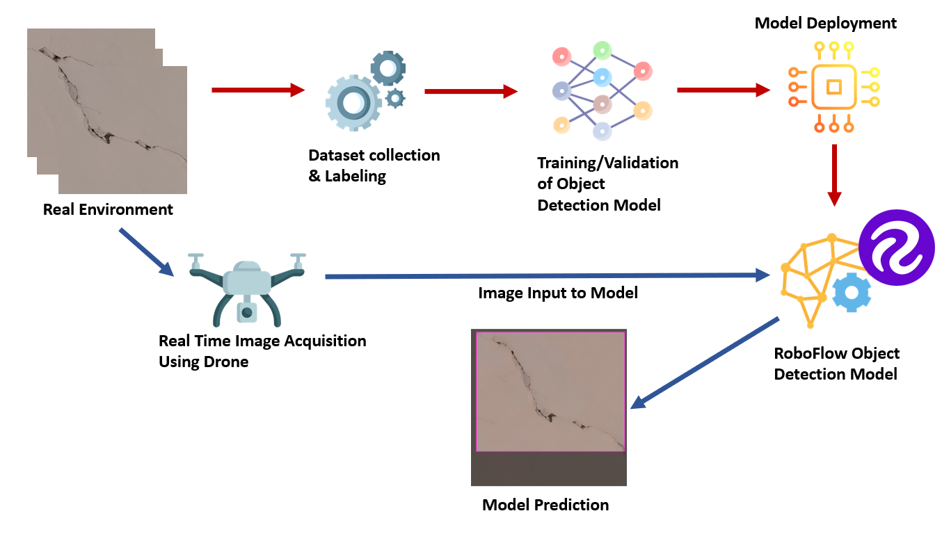
The system is built by collecting images of the cracks in buildings and then labeling and training a model using the annotated data. The Roboflow platform is used to label images and prepare a model that is trained on those images. In addition, Roboflow provides a on-demand API that, given an image or video, returns results from a hosted version of the model. This API is queried using a Python script.
The below diagram shows the process of building the project and how data is fed into the Roboflow model:
Below, we will discuss each of the components involved in building this project.
Project Requirements
To build this project, the following pieces of equipment are needed:
- Quadcopter Drone Kit;
- AI Thinker ESP32 CAM Development Board;
- A Roboflow account and;
- A Python development environment.
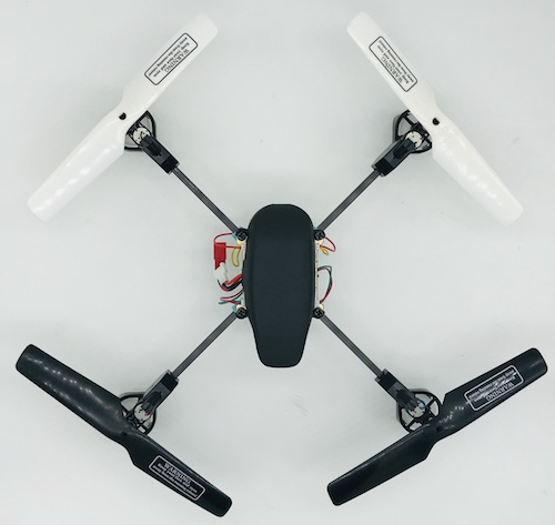
This example uses a Big Quad Expension Drone Kit and Primus X Flight controller from dronaaviation.com. You can use any other drone kit for this project. The image below shows the drone used to collect data and for the project.
The drone has the following specifications:
- 4 x geared 8.5mm Motors with arms
- 1 set of 135mm Propellers
- 1 x Flight Controller
- 1 x 1200 mAH battery
Here's a photo of the drone:

Step 1: Collecting and Labeling Images for the Project
Different images of cracks on a building wall were collected. In total, 755 images sized 800x800 pixels. Roboflow was used to resize these images to 640x640, a standard transformation applied before training. Roboflow then split up the images into a train, test, and validate split:
- 527 images used for training.
- 149 images used for validation.
- 79 images used for testing.
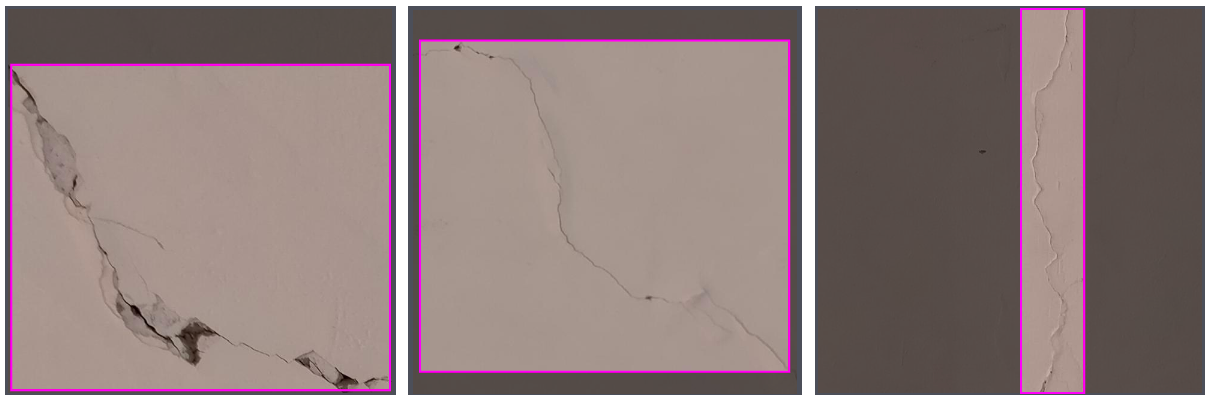
Here is an example of some annotated images:
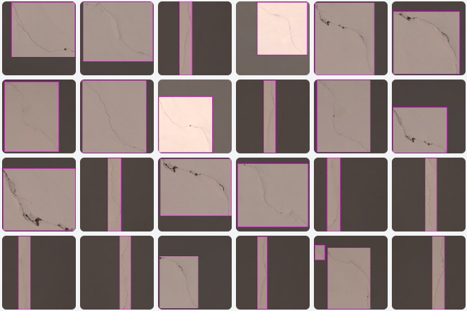
Each image in the dataset is labeled for object detection using a rectangle "bounding box" tool in the Roboflow platform. The following figure depicts how the different images are labeled:
Step 2: Training The Model
After the dataset is labeled, Roboflow Train was used to manage and host training the model. To train the model using Roboflow, click the ‘Start Training’ button present in the interface:
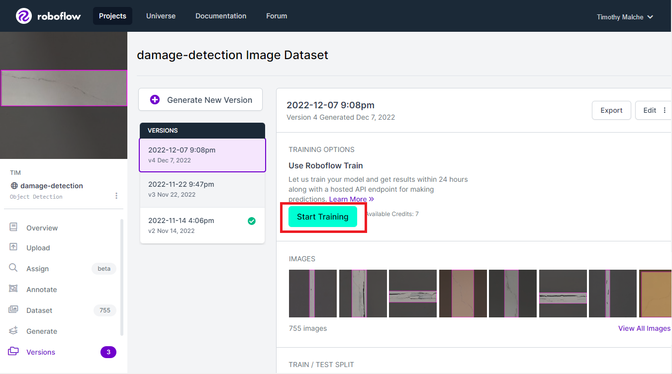
Upon pressing the start button, you'll be presented with the following options:
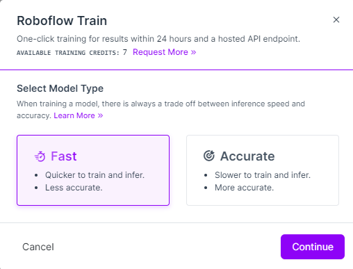
This gives two options for training, ‘Fast’ and ‘Accurate’. You can choose any of these. This project used ‘Accurate’ to achieve more accuracy from the model, even though training would take longer.
Once you click ‘continue’, you will get another dialog box with three options for training to choose between as illustrated below. These are the following options:
- Train from Previous Checkpoint
- Train from Public Checkpoint
- Train from Scratch
These options are illustrated below:
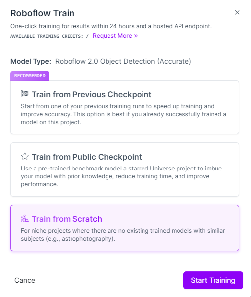
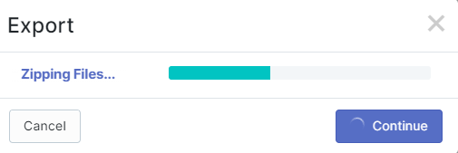
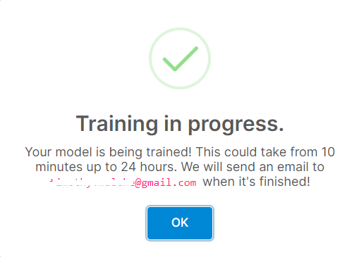
Since I do not have an existing trained model for a similar subject, ‘Training from Scratch’ was chosen which selects the Roboflow 2.0 Object Detection (Accurate) model and trains from scratch. Roboflow first exports the dataset for training and then starts the training as shown below:
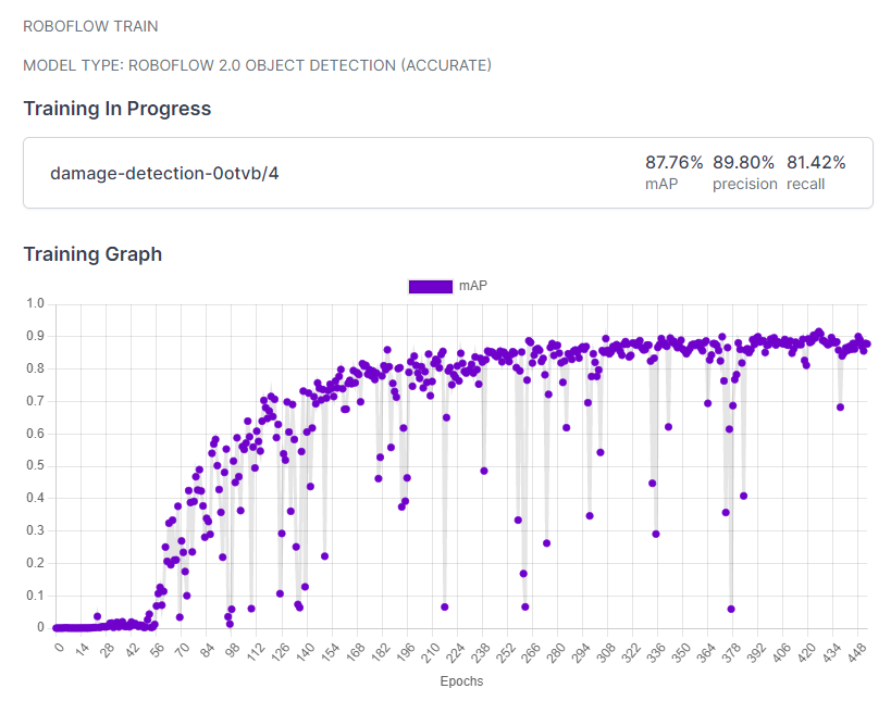
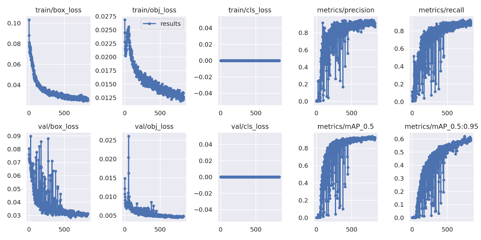
While the model is being trained, Roboflow displays a nice training graph which is helpful in understanding how the model is being trained.
The graph shows the performance of a model across different "epochs". An epoch is a single iteration in the training process. The graph shows the Mean Average Precision (mAP) metric, which measures model performance, changing as the model trains on more epochs. mAP should go up over time.
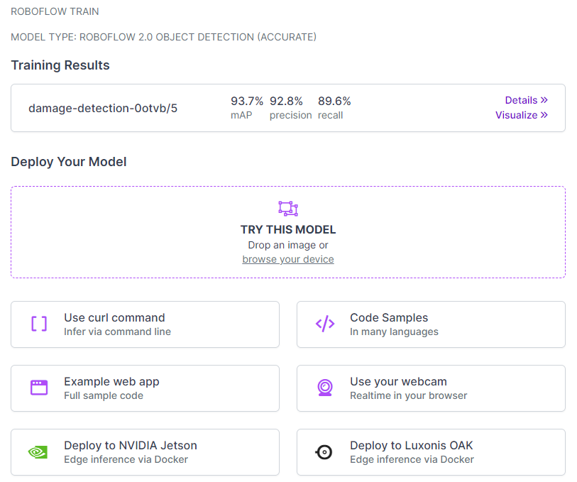
After the model was trained, we see mAP 93.7%, precision 92.8%, recall 89.6% with average precision by class 92% on Validation Set and 89% on Test Set.
The following figure shows more detailed training graphs. These graphs illustrate changes in precision, recall, and more:
Step 3: Using the Model for Prediction
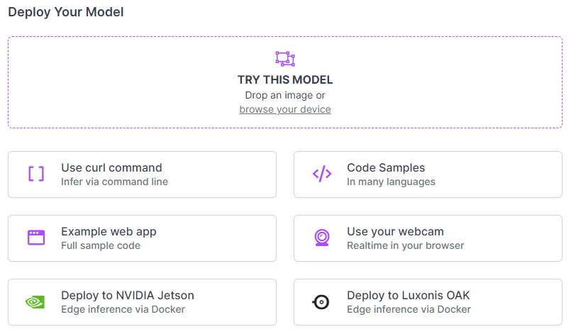
Once the model is trained, it is automatically deployed on the Roboflow platform and it is available to be used. Roboflow provides various options for testing and deploying the model, from trying the model live in one's browser to deploying the project to edge devices like the Luxonis OAK. This is shown in the figure below.
This project uses code from the Roboflow GitHub to use the model on a personal computer. The code accepts a camera feed and runs video data from the camera through the trained model.
Before the model can be used in the Python script, the "roboflow_config.json" configuration file needs to be populated with a few values. These values contain information about the model and an API key so we can authenticate with Roboflow.
{
    "__comment1": "Obtain these values via Roboflow",
    "ROBOFLOW_API_KEY": "XXXXXXXXXX",
    "ROBOFLOW_WORKSPACE_ID": "XXXXXXXXXX",
    "ROBOFLOW_MODEL_ID": "XXXXXXXXXX",
    "ROBOFLOW_VERSION_NUMBER": "XXXXXXXXXX",
    "ROBOFLOW_SIZE": XXXX,
    "EMAIL": "XXXXXXXXXX",
    "__comment2": "The following are only needed for infer-async.py",
    "FRAMERATE": 24,
    "BUFFER": 0.5
}
Above, replace the ROBOFLOW_API_KEY, ROBOFLOW_WORKSPACE_ID, ROBOFLOW_MODEL_ID, ROBOFLOW_VERSION_NUMBER, ROBOFLOW_SIZE and EMAIL values as required.
In the Python code below, we have added "confidence" parameter set to 20 because we want to highlight every crack that has been detected even with less precision. The "20" value means that any prediction with a confidence level of over 20% will be returned by the model.
upload_url = "".join([
    "https://detect.roboflow.com/",
    ROBOFLOW_MODEL_ID, "/",
    ROBOFLOW_VERSION_NUMBER,
    "?api_key=",
    ROBOFLOW_API_KEY,
    "&format=json",
    "&confidence=20",
    "&stroke=5"
])
In the following code lines in the Python source file, we have used the URL of the ESP32 camera, which is mounted on the drone. Data from the camera will be fed back to the model to identify cracks in buildings. This URL may be different for your ESP32 cam deployment.
URL = "http://192.168.175.247"
video = cv2.VideoCapture(URL + ":81/stream")
The code above should replace the following line of code:
video = cv2.VideoCapture(0)The detailed tutorial on how to prepare and use ESP32 Cam for this project is described here.
We can run our adjusted version of the aforementioned Python script that we copied earlier using the following command:
python script.pyA public version of this project called damage-detection is available on Roboflow Universe that you can use to test the model. From Roboflow Universe, you can also download the dataset on which the model was trained.
The Results
Now it is time to try the model. Let's run the model with the drone pointed at a crack in a wall. The results are below:
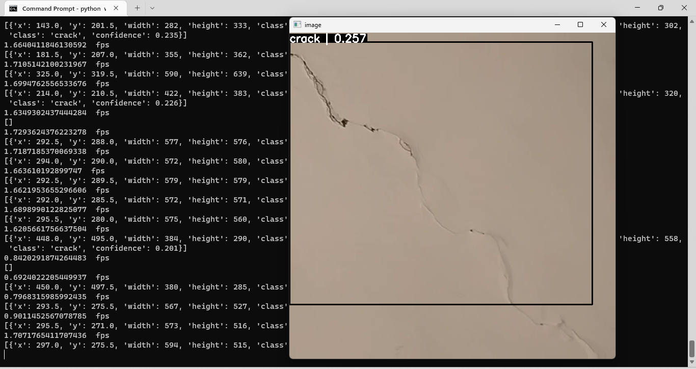
In the image above, a crack is identified in the wall at which the drone is pointed. We could use this information as part of a surveying report that catalogs structural issues on the building. Below, we show the camera pointed at a wall with two different backgrounds that features a crack across each background:
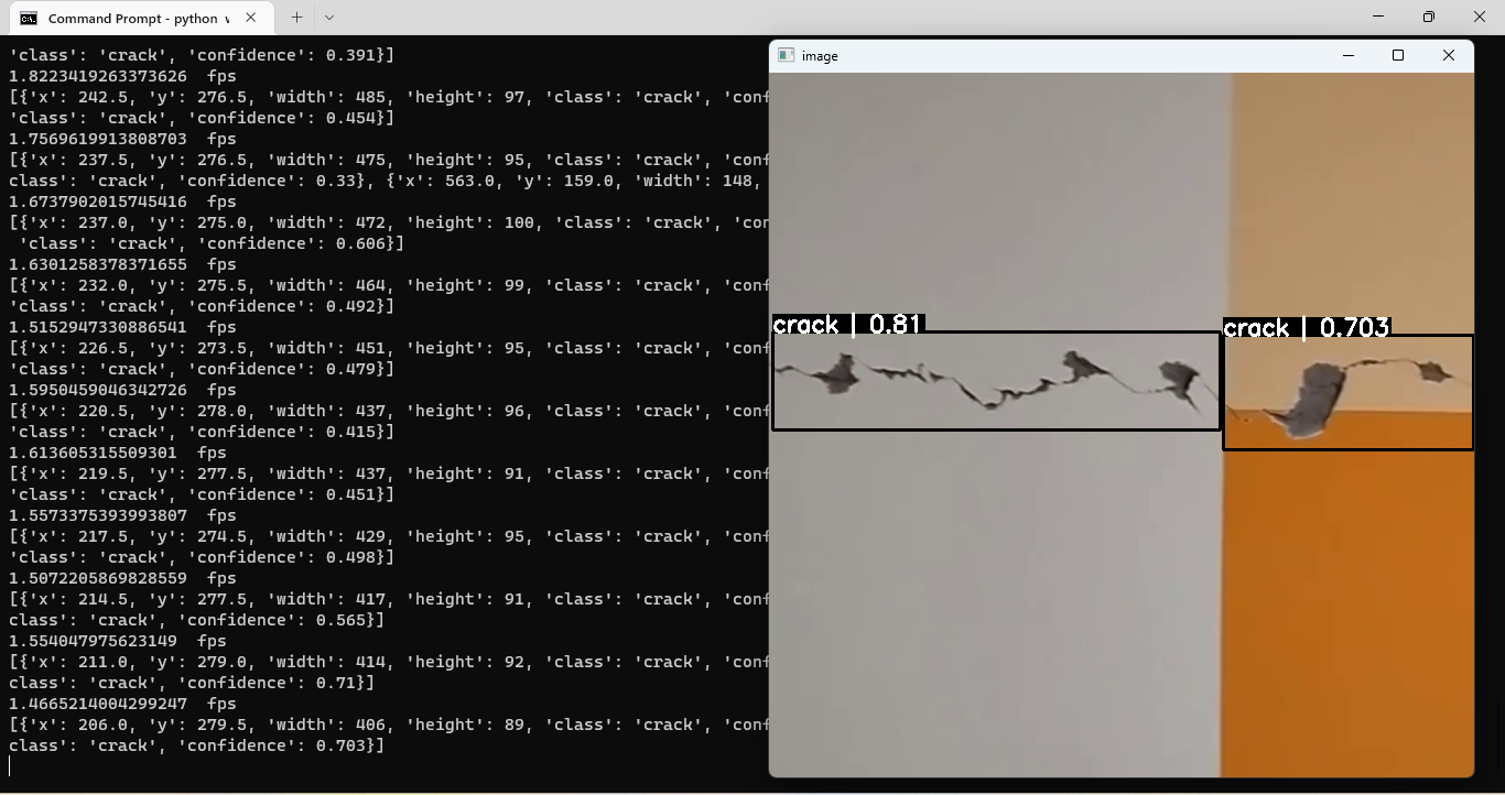
In the image above, two cracks are identified. This shows our model is working as expected. Given drone footage, cracks are successfully identified in walls. In the terminal output, each crack is given the class "crack".
We could expand our model to identify other types of structural damage, such as chipped tiles on a roof. This would involve following the same process that we discussed at the beginning of the article: collect representative data of the type of structural damage, annotate the damaged features in the images, then train a model that uses the data.
Following the instructions above and using the public dataset that accompanies this project, you could build your own drone that identifies cracks in structures. Happy building!
Cite this Post
Use the following entry to cite this post in your research:
Timothy M. (Dec 15, 2022). Computer Vision Assisted Structural Damage Inspection Using Drones. Roboflow Blog: https://blog.roboflow.com/computer-vision-assisted-structural-damage-inspection-using-drones/