

To connect computer vision to a PLC, run your model in a Roboflow Workflow that turns detections into a decision (reject_signal = true), then write that value to a PLC tag over OPC UA, Modbus TCP, or EtherNet/IP using the PLC Writer block. The vision system decides what happened; the PLC keeps ownership of timing, interlocks, and the physical reject, which is what makes the integration production-safe.
Computer vision Programmable Logic Controller (PLC) integration connects what a vision system sees with what a machine actually does. A computer vision model can detect a damaged package, missing component, incorrect label, unsafe condition, or defective product. But a detection alone does not change the manufacturing process. If a defective part continues down the conveyor and ships to a customer, the vision system has identified the problem without solving it.
Connecting the vision system to a PLC closes this gap. A production computer vision system can inspect a part, make a decision, send that decision to the PLC, and cause a physical action on the line. The PLC can activate a reject mechanism, divert a product, stop equipment, or signal an operator. The important part is not just detecting the object, but also turning the detection into a reliable, correctly timed machine signal.
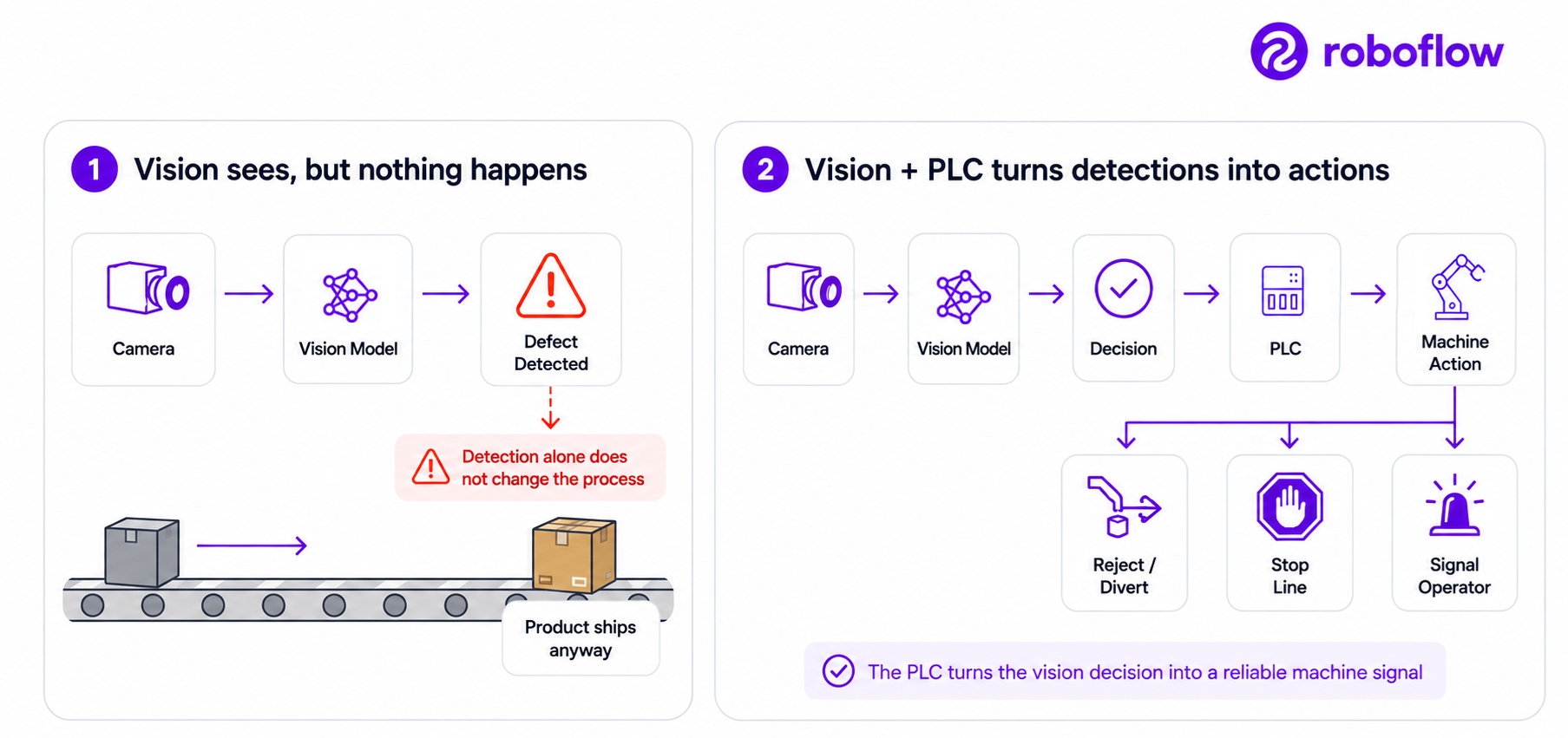
In this guide, I will explain how computer vision PLC integration works, how to connect a camera to a PLC through common industrial protocols, where Roboflow fits into the architecture, and what needs to be considered before putting the system on a production line.
Why Connect Computer Vision to a PLC?
A camera gives a manufacturing system a new type of sensor. Traditional PLC inputs usually represent simple states. A photoelectric sensor may tell the PLC that a product is present. A proximity sensor may indicate that a cylinder reached its position. A pressure sensor provides a process measurement. A vision system can provide much richer information.
For example, a computer vision model can determine that a product is present and identify whether it has the correct components, whether its label is aligned, whether its surface contains a defect, or whether an assembly operation was completed correctly. The PLC then turns that visual information into an operational response. Following are some common actions:
- Reject or divert a product: The PLC can activate an air jet, pneumatic pusher, diverter gate, or reject mechanism when the vision system identifies a defective item.
- Pick and place with a robotic arm: The PLC can command a robotic arm to pick, remove, reposition, or sort a detected product based on the vision result.
- Stop or pause the line: The PLC can stop or pause production when the system detects a serious defect, jam, missing component, or other predefined condition.
- Signal an operator: The PLC can activate a stack light, andon light, buzzer, HMI message, or other alert so an operator can respond.
The vision model should generally not control the machine actuator directly. Instead, the vision application determines something such as:
reject_required = true
or:
inspection_result = FAIL
The PLC receives that state and executes the machine sequence. This separation matters because the PLC is designed to provide deterministic machine control. It already knows whether the line is running, whether the reject station is available, whether safety interlocks are satisfied, and when an actuator should fire. Computer vision adds visual intelligence to that control system. The result is:
Vision decides what happened. The PLC decides how the machine responds.
Computer Vision PLC Integration Architecture
A practical Roboflow-based architecture can be represented as:
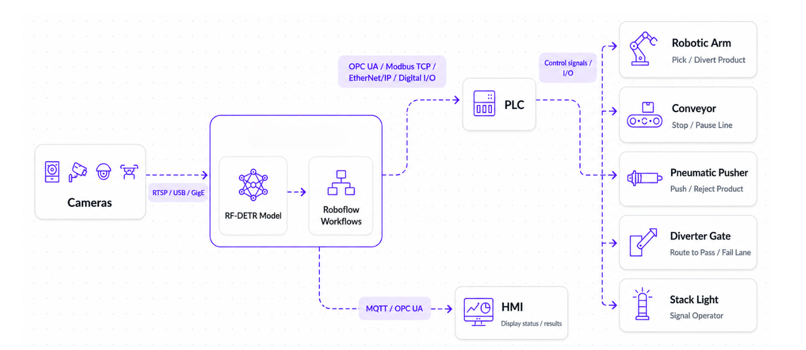
Roboflow Workflows provide the application layer between the model prediction and the industrial system. A Workflow can combine models with filtering, tracking, counting, conditional logic, custom Python, external integrations, and other processing blocks.
Camera
The camera captures the inspection area. Depending on the application, this could be a USB camera, industrial camera, RTSP camera, or another supported camera source. Roboflow Workflows can be used with USB, Basler, and RTSP-capable cameras.
RF-DETR Inference
The image is processed by a computer vision model. For example, you could train an RF-DETR object detection model to recognize defects such as missing component, damaged packaging, incorrect assembly, surface defect, foreign material, broken product, or another visual condition specific to the production process. RF-DETR is designed for real-time detection and can be deployed using Roboflow Inference on edge hardware. The output might look conceptually like:
class: damaged_package
confidence: 0.93
x: 712
y: 420
width: 186
height: 145
At this stage, the model has made a prediction. It has not yet decided what the machine should do.
Workflow Logic
The Roboflow Workflow turns raw predictions into an operational decision. For example, the Workflow may define:
IF class == "damaged_package"
AND confidence >= 0.80
AND object is inside inspection zone
THEN reject_required = true
A more advanced Workflow could also track the object across multiple video frames, check whether the defect remains visible for several frames, ensure that the same item is not counted twice, and record the event before sending the result to the PLC.
Roboflow Workflows can be deployed to Roboflow-managed infrastructure or self-hosted with Roboflow Inference. For production lines where latency is important, running the Workflow on hardware close to the camera can reduce dependence on network round trips.
Why Edge Inference Matters for PLC Integration
Timing is one of the biggest differences between a computer vision demo and a computer vision system deployed on a production line. Imagine that a product passes underneath the inspection camera and then reaches a pneumatic reject mechanism. The available decision time depends approximately on:
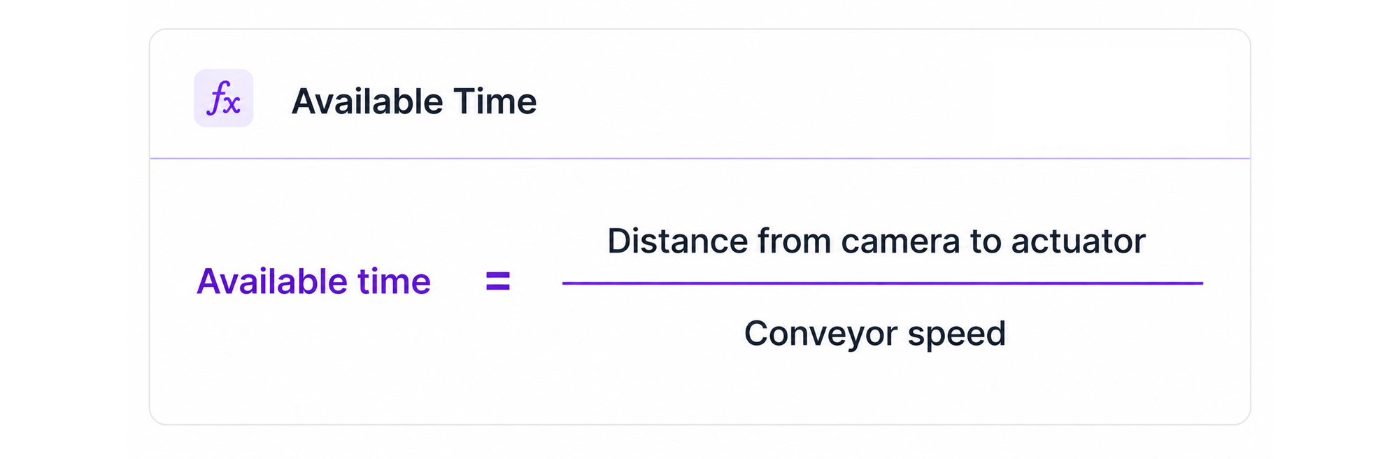
But the computer vision application cannot use this entire period. The total system timing also includes camera exposure, image transfer, inference, Workflow processing, communication with the PLC, PLC scan time, actuator response time, and a safety margin. A more realistic timing budget is:
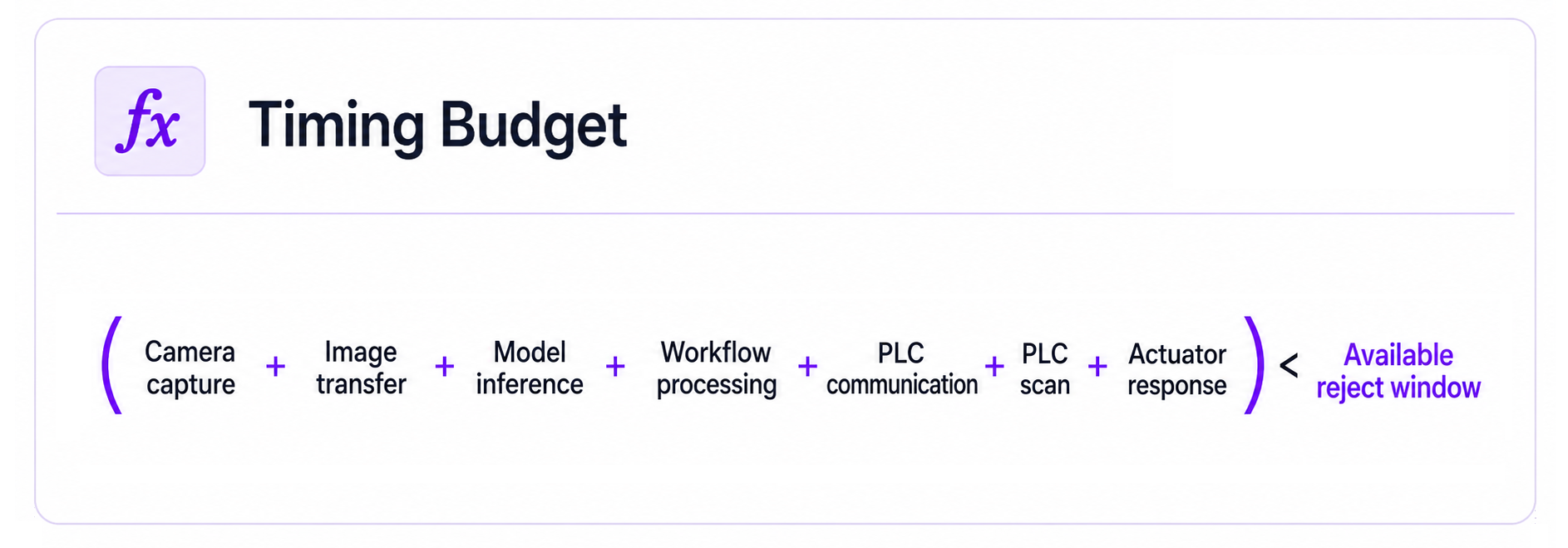
This is one reason edge deployment is important for machine-control applications. Sending every frame to a remote cloud server introduces network latency and additional variability. That may be acceptable for applications such as analytics or offline inspection, but it can become a problem when the product is moving and the machine needs a decision within a tightly defined time window. Roboflow Inference can run models and Workflows on your own hardware and is intended for applications requiring real-time processing at the edge. Roboflow also provides Deployment Manager for supported enterprise deployments to configure cameras, deploy Workflows, and monitor edge devices.
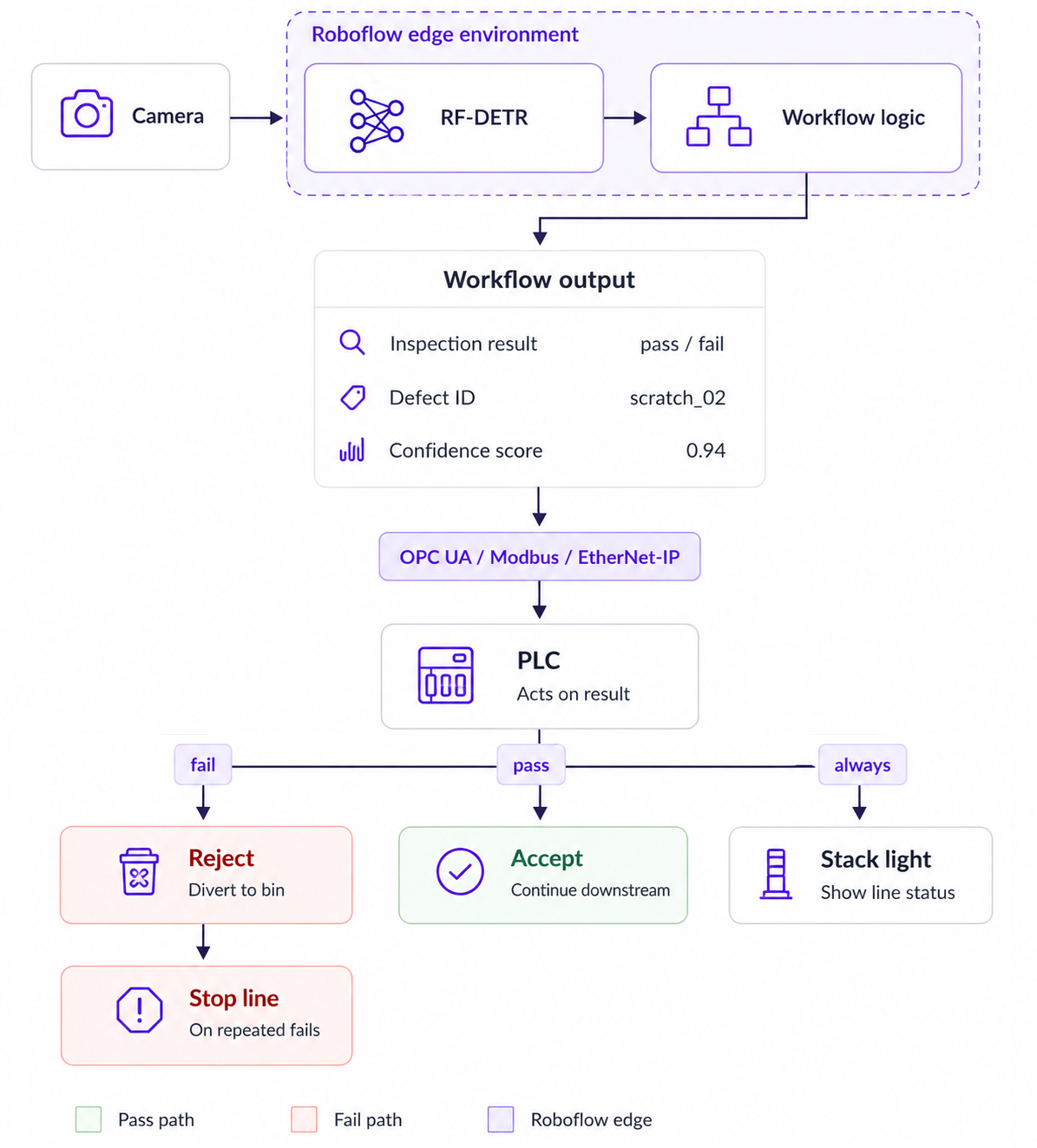
The important architectural boundary is between the vision decision and machine control. The Workflow determines what was seen. The PLC continues to own the machine sequence.
How Vision Systems Talk to PLCs
A vision system can send inspection results to a PLC using OPC UA, Modbus TCP, EtherNet/IP, or digital I/O. The right option depends mainly on the PLC, the amount of data being sent, and the existing factory network. Roboflow Workflows can route model outputs into industrial systems using OPC UA and PLC-oriented integrations.
OPC UA
OPC UA is useful when the Workflow needs to send structured inspection data such as pass/fail, defect class, confidence, or counts. The OPC UA Writer Sink can write Workflow values directly to OPC UA tags that are available to PLCs, SCADA systems, and dashboards. The Property Definition block converts the model result into a value such as a Boolean, count, or defect code, and the OPC UA Writer Sink writes that value to the configured tag.
Modbus TCP
Modbus TCP is suitable when the PLC expects simple coils or registers. It is older and simpler than OPC UA. A Workflow can write a named tag value and that name is mapped to a coil or register on the PLC side, so the mapping is agreed once during setup rather than handled in your Workflow.
A Workflow can send a reject Boolean, a defect code, or a defect count this way. Modbus is very widely supported, which often makes it the easiest option on older equipment.
EtherNet/IP
EtherNet/IP is commonly used when the vision system needs to exchange PLC tags. The Workflow produces the inspection result and that result is written to a PLC tag such as Vision_Reject, Vision_Pass, or Vision_Confidence.
Digital I/O
For very simple applications, the PLC may only need a binary signal, one state for pass and the other for reject. In this case, the vision decision can ultimately be converted into a digital input to the PLC through appropriate industrial I/O hardware. This is simple, but it cannot carry richer information such as defect class, confidence, counts, or part identifiers.
Worked Example: Detect a Defect and Trigger a Reject
Consider a packaging line. Packages move beneath a camera before reaching a pneumatic reject station. An RF-DETR model has been trained to detect a class called damaged_package, package_with_hole. The objective is simple:
When a damaged package is detected, tell the PLC which product should be rejected.
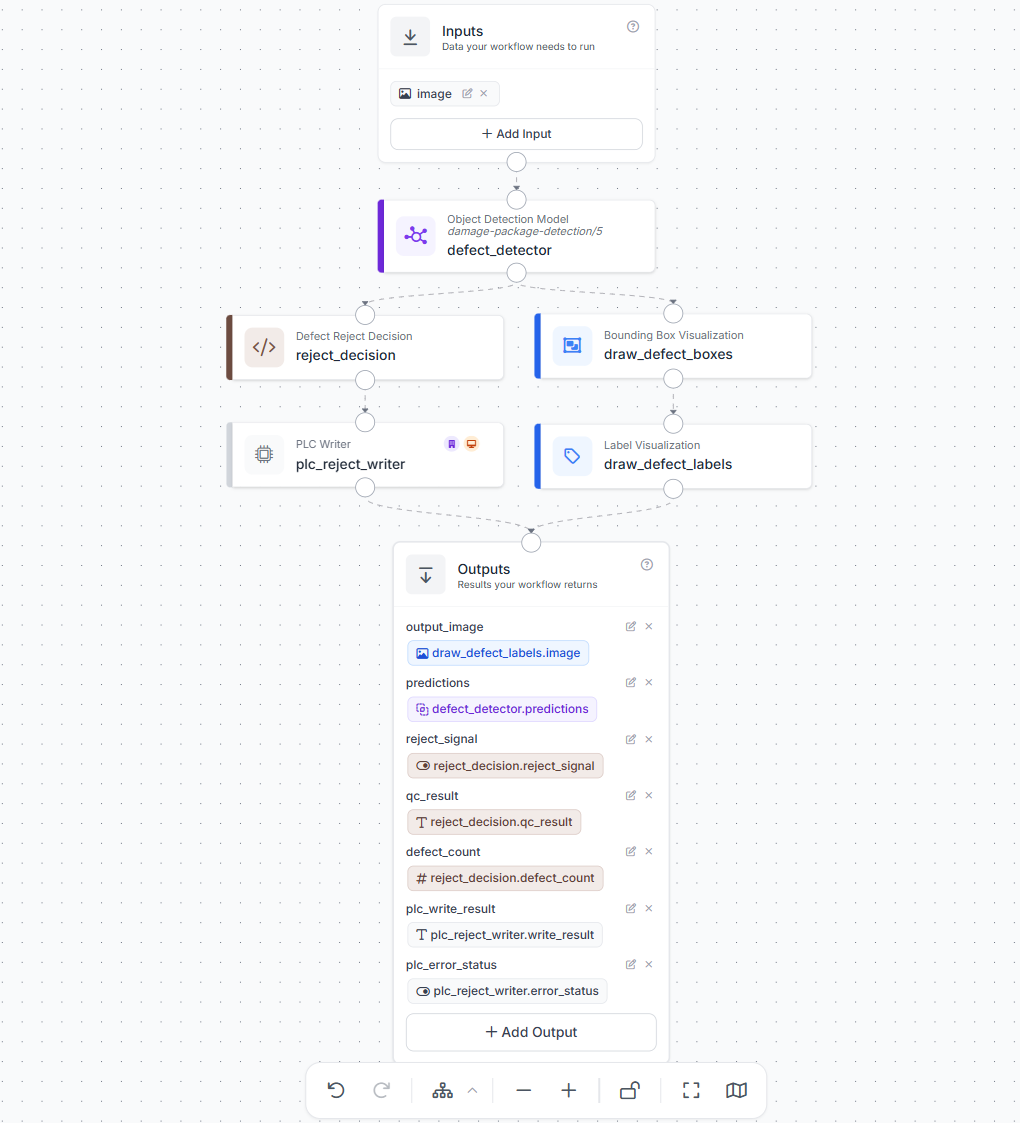
Here's what the example workflow looks like.
Step 1: Detect the Defect
The camera image enters the Roboflow Workflow and is passed to the defect_detector Object Detection Model. For example, the model may detect:
class = damaged_package
confidence = 0.91
The model predictions are then sent to two branches. One branch makes the reject decision, while the other draws bounding boxes and labels for visual review.
Step 2: Convert the Detection into a Reject Decision
The model predictions are passed to the custom Python block named reject_decision. In this example, the logic is simple, count the detections. If at least one defect is detected, generate a reject signal and mark the inspection as failed.
def run(self, predictions):
    defect_count = int(len(predictions)) if predictions is not None else 0
    reject_signal = defect_count > 0
    qc_result = "fail" if reject_signal else "pass"

    return {
        "reject_signal": bool(reject_signal),
        "qc_result": qc_result,
        "defect_count": defect_count,
     }
For example:
defect_count = 2
reject_signal = true
qc_result = fail
If no defect is detected:
defect_count = 0
reject_signal = false
qc_result = pass
The current Workflow uses this simple detection-count rule for demonstration. In a production system, the Custom Python blocks can also check confidence thresholds, inspection regions, object tracking, or other conditions before generating the reject signal.
Step 3: Write the Signal to the PLC
The Boolean reject_signal is passed to the PLC Writer block named plc_reject_writer. Conceptually:
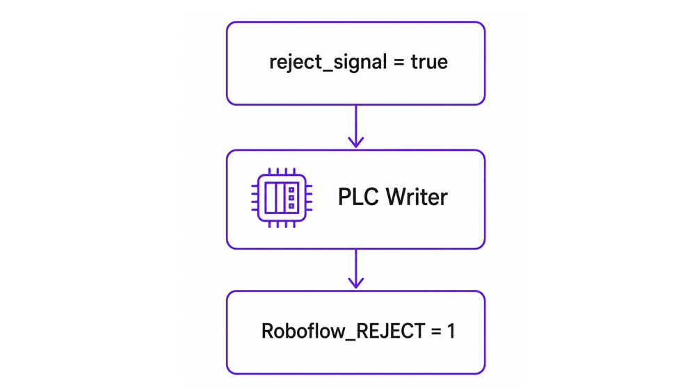
The PLC Writer is the handoff between the Roboflow Workflow and the PLC. When enabled and connected to the PLC, it can write the result to a PLC tag such as Roboflow_REJECT.
Step 4: Let the PLC Execute the Machine Sequence
The computer vision system only tells the PLC that the product should be rejected. The PLC controls the physical reject mechanism. A simple Structured Text example is:
IF Roboflow_REJECT
   AND Product_At_Reject_Station
   AND Reject_System_Ready
THEN
    Activate_Reject_Solenoid := TRUE;
ELSE
    Activate_Reject_Solenoid := FALSE;
END_IF;
This distinction is important. The damaged package may still be some distance away from the reject station when the camera detects it. The PLC therefore needs to make sure that the correct inspected product has reached the reject position before activating the pneumatic reject mechanism. Depending on the line, this can be handled using a timer, shift register, encoder position, or product identifier.
Step 5: Return the Inspection Results
The Workflow also returns useful inspection and PLC information:
output_image
predictions
reject_signal
qc_result
defect_count
plc_write_result
plc_error_status
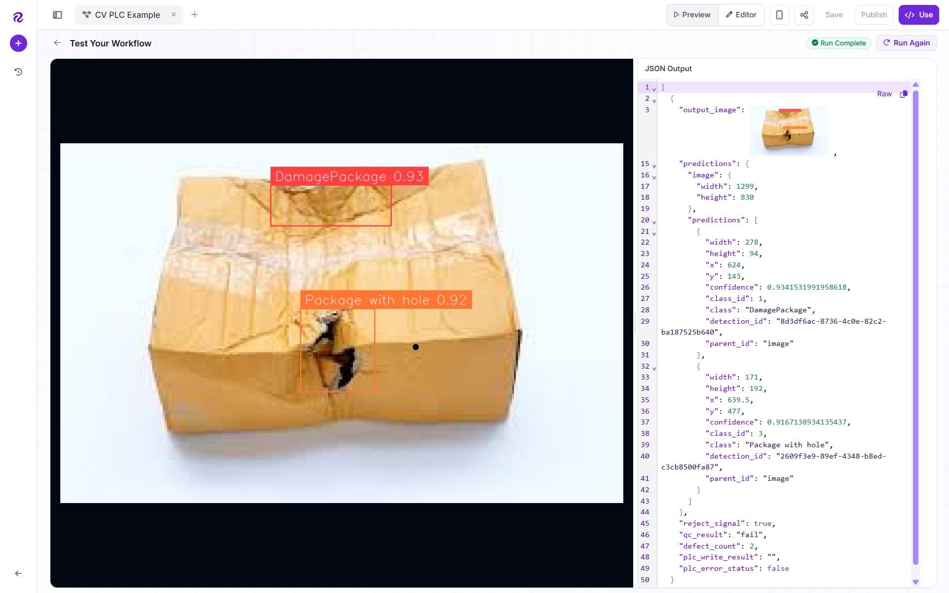
The visualization branch adds bounding boxes and labels to the detected defects, while the decision branch provides the pass/fail result and PLC reject signal. This means the same Workflow provides both a machine-control output and a visual inspection result.
How the example workflow works
The example Workflow demonstrates a complete defect inspection and PLC communication path. The input image first goes to the defect_detector model. Its predictions are then split into two branches. The decision branch sends the predictions to the reject_decision Custom Python block. The block counts the detected defects and returns:
reject_signal
qc_result
defect_count
ladder_logic_example
If at least one defect is detected, reject_signal becomes true and qc_result becomes fail. If no defects are detected, the product receives a pass result. The Boolean reject signal is then passed to the plc_reject_writer PLC Writer, which can write the result to the PLC for use in machine control logic.
The visualization branch sends the same detections through the Bounding Box Visualization and Label Visualization blocks to create an annotated output image showing where the defects were detected. This keeps the PLC decision and the visual inspection evidence available from the same Workflow.
This example workflow uses label defect detection model, so when you run it you will see output similar to following.
Handling Computer Vision PLC Integration Failure Modes
A production vision system needs to handle more than correct detections. Engineers also need to know what happens if inference is too slow, the camera disconnects, the same defect is detected several times, or the PLC does not receive the signal.
Keep Inference Fast Enough
The vision system must make its decision before the product reaches the reject or action point. If processing is too slow, you can use a smaller model, reduce image resolution, simplify the Workflow, use GPU acceleration, trigger the camera only when a product arrives, or run inference on edge hardware. The important question is simple:
Can every product be inspected before the PLC needs to act?
Detect Camera and Connection Failures
A missing camera image should never be treated as a successful inspection. Use a watchdog or heartbeat signal so the PLC knows that the camera and vision system are still running. For example:
Vision_Healthy = TRUE
Camera_Connected = TRUE
Vision_Heartbeat = ACTIVE
If the heartbeat stops, the PLC can alert an operator, switch to manual inspection, reject unverified products, or stop the line.
Prevent False and Repeated Rejects
Do not send every detection directly to the PLC. First, use Workflow logic to check the confidence threshold and confirm that the defect meets the required conditions.
IF confidence > 0.85
AND inside_inspection_region
AND defect_confirmed
THEN
    Reject
ELSE
    Continue
END IF
The confidence threshold helps reduce false rejects. Tracking also makes sure the same product is not rejected again in every video frame. This acts like debounce logic, so one defective product generates only one reject event.
Confirm PLC Communication
The vision system should also know whether the PLC received the result. A heartbeat, acknowledgement, connection status, or inspection ID can be used to check communication. If communication fails, the system should already know what to do i.e. stop the line, reject the product, or send it for manual inspection.
Log Every Action as a Vision Event
When the system rejects a product, operators should be able to see why. Roboflow Vision Events can store the image, timestamp, prediction, confidence, inspection result, and related metadata. A simple event might contain:
timestamp
inspection_id
defect_class
confidence
image
reject_required
PLC_acknowledged
This creates an audit trail from what the camera saw to what the Workflow decided and what action was sent to the PLC, making false rejects and recurring production problems easier to investigate.
Beyond the Reject Signal
Computer vision PLC integration can do more than send a simple Reject = 1 signal. Once a Workflow produces a structured inspection result, the same data can support quality records, operator alerts, and coordination across multiple stations.
Send Inspection Results to MES
The PLC handles the immediate machine action, while a Manufacturing Execution System (MES) can store the longer-term quality record. A Workflow can send information such as the defect type, timestamp, part number, confidence score, inspection result, and supporting image.
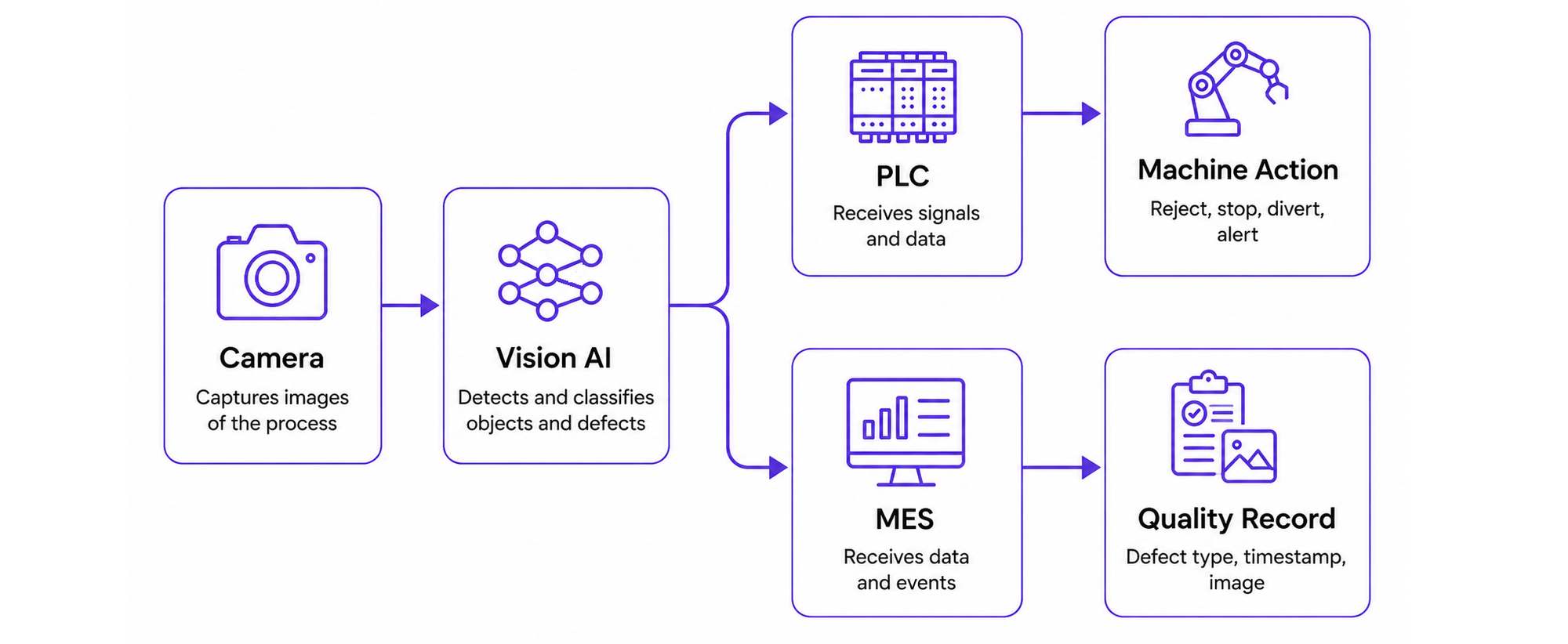
This allows one inspection to support both real-time control and quality traceability.
Andon and Operator Systems
Not every vision result needs to stop the machine. Some events are better sent to an operator for attention. For example, a Workflow can respond differently depending on what it detects:
- A serious, high-confidence defect can trigger an automatic reject.
- Repeated defects can activate a stack light or andon signal.
- An unusual or low-confidence result can be sent to an operator for manual review.
The Workflow decides which response is appropriate, while the PLC can activate the stack light, update the HMI, or trigger another operator alert.
Coordinate Multiple Vision Stations
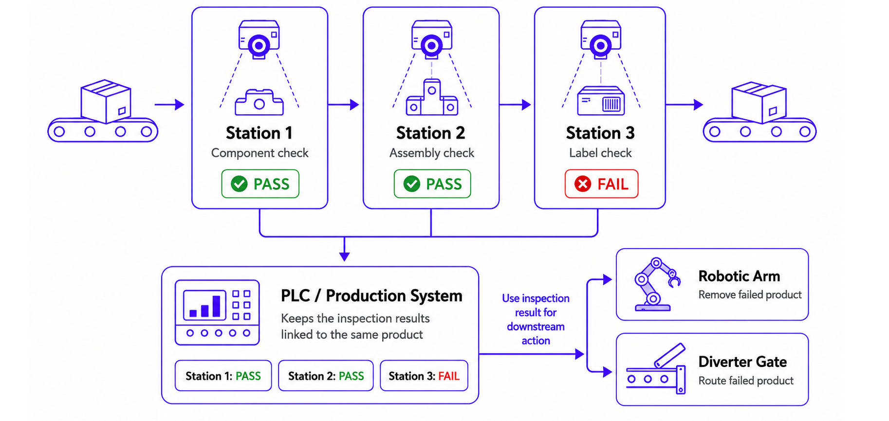
A product can be checked at several points as it moves along the production line. Each station performs a different inspection and records the result.
Station 1: Component check → PASS
Station 2: Assembly check  → PASS
Station 3: Label check     → FAIL
The PLC or production system keeps these results linked to the same product. If a later inspection fails, the system can use that result to trigger a downstream action, such as asking a robotic arm or diverter gate to remove the product from the line.
Connecting a Camera to a PLC with Roboflow
A Roboflow-based PLC integration can be understood as a simple flow:
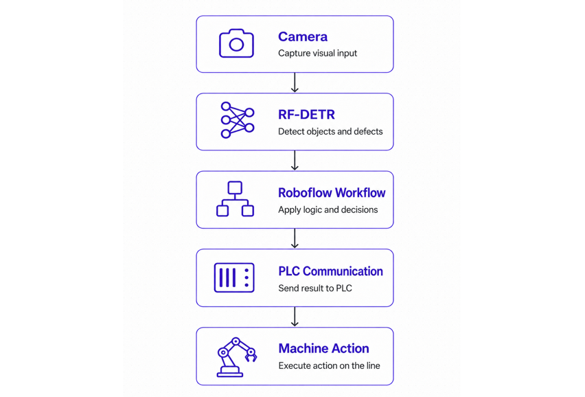
The camera captures the product, RF-DETR detects what is visible, and the Roboflow Workflow converts those predictions into a production decision. That result is then sent to the PLC, which controls the actual machine action.
This separation keeps each part focused on its job: the model handles visual understanding, the Workflow handles decision logic, and the PLC handles machine timing and control. The same Workflow can also run with Roboflow Inference on edge hardware when low-latency processing is required close to the production line.
Learn more about how cloud connected AI products run on-prem.


Cite this Post
Use the following entry to cite this post in your research:
Timothy M. (Aug 3, 2026). Computer Vision PLC Integration: Turn Detections into Machine Actions. Roboflow Blog: https://blog.roboflow.com/computer-vision-plc-integration/